


C. Thermostat Bulb Positioning
BEFORE REPLACING, TEST THERMOSTATS:
These operational problems can easily be
corrected by thermostat bulb positioning.
Keating’s patented thermostat application is
accurate within 2°F of the dial setting between
250°F – 350°F. This accuracy is attained only if the
thermostat bulb is placed properly against the heat
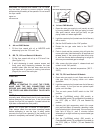
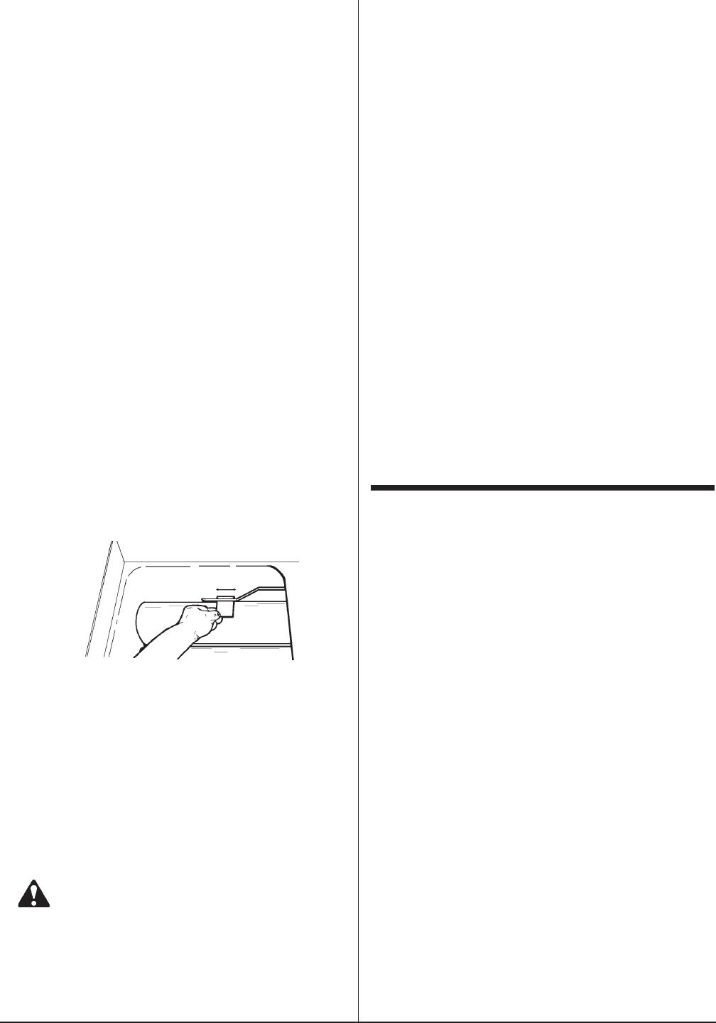
transfer tube. To quickly and accurately test for
proper bulb placement, a single thickness of writing
paper should be pulled through between the tube
and the bulb with medium resistance.*
1. *For gas fryers 14":
The end of thermostat bulb should touch the burner
tube.
2. For gas fryers 10x11, 18 & up:
If the bulb is too loose, the paper will slip through
with little or no resistance. A fryer with a thermostat
bulb that is too loose will overshoot.
Overshoot: The thermostat takes a long time to
cycle and then misses its preset temperature by
20°F - 40°F yielding a poor quality product.
If the bulb is too tight, the paper will either not pull
through or it will tear. A fryer with a thermostat bulb
that is too tight will short cycle.
Short Cycle: The thermostat will cycle rapidly while
the fryer is in the idle mode; the temperature will be
erratic.
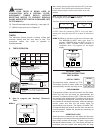
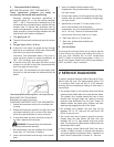
Thermostat Bulb Positioning 10x11, 18 & up Fryer Gas
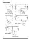
REQUIRED TEST EQUIPMENT:
Multimeter (for testing continuity)
CHECKING CONTINUITY WITH THE MULTIMETER
1. Rotate the thermostat shaft until an audible click
is heard.
2. Rotate the thermostat shaft left and right ten times
causing the switch to click on and off ten times,
while using the Multimeter to verify continuity.
3. If the switch does not show continuity during all
ten trials, replace the thermostat.
WARNING: Disassembling the thermostat
will void the thermostat warranty.
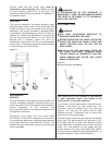
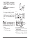
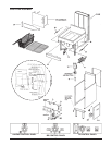
1. Set compression ring onto capillary end of bulb
finger tight, 1/2” from end of capillary.
2. Insert new thermostat bulb through control panel
back.
3. Apply oil resistant flexible sealant onto
compression fitting thread before installing fitting
into fryer vessel.
4. Position bent portion of bulb against far right heat
transfer tube and install compression fitting snugly
into fryer vessel.
5. Adjust bulb so at least 2” of bent portion of it is
next to heat transfer tube and tighten
compression nut onto compression fitting for fryer
10x11, 18 & up. The end of thermostat bulb
should touch the burner tube for 14" fryers.
6. Refill fryer with oil to “fill level line”.
7. Start fryer, preheat and calibrate with
thermometer.
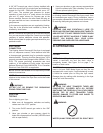
D. Hi-Limit Check
The manual Hi-Limit test button can be used to test the
Hi-Limit Control by pushing and holding the button in
until the fryer reaches the Hi-Limit temperature
(425°F). Place an accurate thermometer in the oil. If
the Hi-Limit Control doesn’t shut off the fryer between
425°F and 450°F, have it replaced.
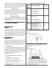
V SERVICE DIAGNOSIS
A properly adjusted Keating Instant Recovery® Fryer,
with no load, will cycle “On” approximately every 2-1/2
to 3 minutes. Each cycle will last 15 to 25 seconds,
ensuring that the temperature setting is held within a
narrow band.
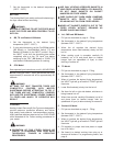
The burners when on will produce clear blue flames
directed at the inside walls of the heat transfer tubes.
The radiant’s fins, located towards the rear of each
transfer tube, will glow bright red, helping to ensure
optimum heat distribution into the fryer vessel. All
radiants should be pulled gently forward until their
retaining clips engage the rear of the tubes.
On constant pilot models, the pilot light will be
between 3/8” to 1/2” high and will use about 180
BTU’s of gas per hour.
The runner pilot tube is used to ignite the burners.
Flames from the tube should be clear blue and
between 3/8” to 1/2” high spread across the entire
tube. The burners will ignite almost instantly after the
thermostat calls for heat.
Every Keating Instant Recovery® Gas Fryer has a
number of safety controls to ensure safe operation
and guard against component failure. Operation of
each control is explained in Section VI – Service.
11