


- iii -
TABLE OF CONTENTS
Page
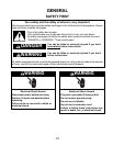
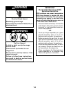
GENERAL............................................................................................................................... 1-1
Safety First......................................................................................................................... 1-1
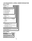
KitchenAid Model & Serial Number Designations.............................................................. 1-3
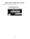
Model & Serial Number Label Location ............................................................................. 1-4
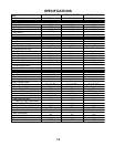
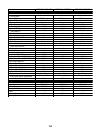
Specifications..................................................................................................................... 1-5
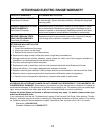
KitchenAid Electric Range Warranty.................................................................................. 1-7
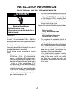
INSTALLATION INFORMATION ........................................................................................... 2-1
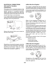
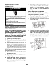
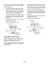
Electrical Supply Requirements ......................................................................................... 2-1
Moving The Range ............................................................................................................ 2-8
THEORY OF OPERATION ..................................................................................................... 3-1
Air Flow—Rear Panel ........................................................................................................ 3-1
Cooling Fan Air Flow ......................................................................................................... 3-2
The Bimetal Switches ........................................................................................................ 3-3
The Surface Element Limiter ............................................................................................. 3-4
The Door Lock Solenoid & Door Latch Switch................................................................... 3-5
How The Self-Clean Cycle Works ..................................................................................... 3-6
COMPONENT ACCESS ......................................................................................................... 4-1
Component Locations ........................................................................................................ 4-1
Removing The Control Panel, An Infinite Switch & Bimetal Switch ................................... 4-2
Removing The Electronic Oven Control And An Indicator Light ........................................ 4-4
Removing An Element & Limiter And The Hot Surface Indicator Assembly ...................... 4-5
Removing The Cooktop Glass ........................................................................................... 4-7
Removing The Door Latch Assembly & The Door Switch ............................................... 4-10
Removing The Dual Broil Element And The Hidden Bake Element ................................ 4-12
Removing The Convection Bake Element & Fan Motor .................................................. 4-14
Removing An Oven Light Socket Assembly .................................................................... 4-16
Removing The Meat Probe Jack ..................................................................................... 4-17
Removing The Oven Temperature Sensor ...................................................................... 4-18
Removing A Side Panel ................................................................................................... 4-19
Removing The Double Line Break (DLB) Relay And The Cooling Fan Motor ................ 4-20
Removing The Oven Door ............................................................................................... 4-22
Removing The Decorative Glass, The Oven Door Handle, The Hinges,
And The Oven Door Glass........................................................................................... 4-23
Removing The Oven Door Gasket................................................................................... 4-25