


34
11
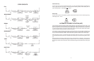
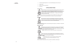
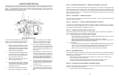
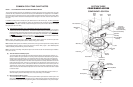
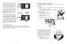
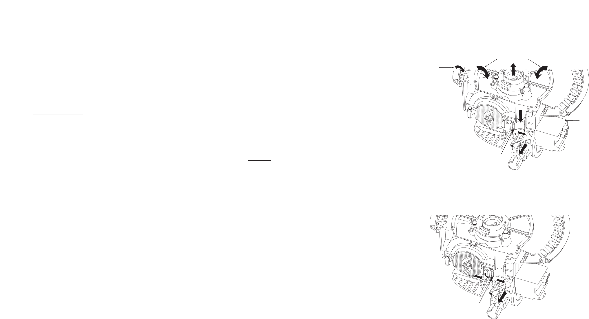
Drain Function
1. During the Drain function, a separate drain pump motor (1) is started while the main wash
pump motor continues to operate for 1 minute. This accomplishes three goals.
2. First, the jets on the underside of the lower spray arm continue to flush soils from the accumu-
lator screen while the water is drained from the unit. (2)
3. Second, negative pressure in the main wash pump inlet chamber keeps the check valve closed,
allowing the drain pump to remove soiled water from the accumulator. (3)
4. Third, the spray arms will rinse down the interior of the wash tub while the water is drained,
leaving the inside free of soils. (4)
1
2
3
4
2
5
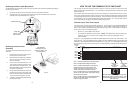
5. The main wash pump then stops, creating positive pressure in the pump’s inlet chamber. This
opens the check valve allowing the remaining water to be drained away. (5)
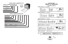
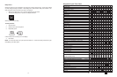
NOTE 5 - NUMERIC CYCLE TIME DISPLAY
Some models with numeric cycle time displays show an animated spinning clock pattern during the
first four intervals of the cycle (intervals 45-42) while sensor based cycle modifications (and true time
remaining) are being determined. Other models simply display the worst case cycle time remaining
(in minutes) until the end of interval 42. See the Model Specifics Table to identify models with numeric
displays and which models exhibit the animated clock pattern. At the end of interval 42,
all models
with numeric displays will begin displaying a corrected cycle time (in minutes). From here on, the
display counts down normally, minute by minute, through the rest of the cycle.
Note: Cycle time does
not include time spent in thermal holds; the time on the display at the start of
the thermal hold is frozen until the end of the thermal hold (see notes 3 & 6).
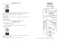
NOTE 6 – WATER HEATING (THERMAL HOLD) STATUS INDICATOR
The Water Heating indicator is turned on during all thermal hold intervals to signal that cycle timing,
display sequencing, and numeric cycle time display countdown operations have been suspended or
frozen while the water is heated to the proper temperature (see note 3).
NOTE 7 – SOAKING/SENSING & SOAKING STATUS INDICATORS
In general, the
Soaking/Sensing indicator is primarily a “sensing” indicator and is turned on during
cycles whenever the control is still making decisions based on sensor inputs. Specifically this includes
all APF intervals, all thermal hold intervals, and the first four intervals of each cycle (see notes 1, 2,
and 3).
The Soaking/Sensing indicator also turns on during “soaking” events like the “soaking/pause” intervals
in the Energy Star low soil/non-sensor version of the Normal cycle (see note 9). A dedicated
Soaking
indicator is available for non-numeric models that will likewise turn on during these “soaking” events
but
not during “sensing” intervals.
NOTE 8 – ‘END-OF-CYCLE’ STATUS INDICATORS – CLEAN and SANITIZED
Both end-of-cycle indicators (Clean and Sanitized) turn on at the end of a cycle and turn off upon
pressing any key or opening and closing the door (note: the indicators stay on as the door is opened
but turn off as soon as the door is closed again).
(a) Clean
Comes on at the end of every cycle except Rinse Only/Quick Rinse.
(b) Sanitized
Comes on at the end of all cycles completed with the Sani Rinse option selected (see note 15).
If the Sani Rinse option is completed successfully, the indicator is turned on steady at the end
of the cycle. If the Sani Rinse was unsuccessful (see below), the indicator will flash ½ second
on, ½ second off, repeatedly, at the end of the cycle. The Sani Rinse will be deemed unsuc-
cessful (& flash the indicator) if:
(1) The thermal hold in the final rinse (interval 15) fails to reach the required 160F/71C
before timing out on its default time limit.
(2) The door is opened and/or power is interrupted between the end of the final rinse
thermal hold (interval 15) and the end of the cycle.