


30
15
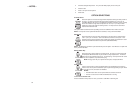
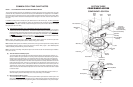
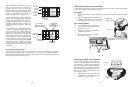
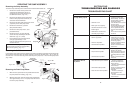
Removing the Electronic Control Board
The electronic control board on the KitchenAid KUD01 Dishwasher is virtually the same configuration
for both the split controls and the full control versions.
ALL MODELS
1. Disconnect the ribbon connector and the wiring harness connectors from the electronic control
board.
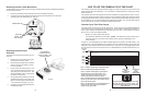
2. Use a flat bladed screwdriver to depress the
holding tabs at the left end of the control board
assembly while pulling up.
(Fig. 3-2, Inset)
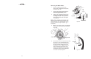
SPLIT CONTROL MODELS
3. Once the Electronic Control Board is re-
moved, a ribbon cable interconnect board
is exposed.
(Fig. 3-3)
4. Unsnap the interconnect board from the
control panel assembly.
5. Disconnect the three ribbon cables from
the interconnect board.
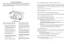
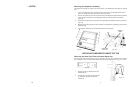
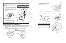
The Door Latch Assembly for both the Split Con-
trol and Full Control versions are essentially the
same assembly. The latch handle is installed in
one of two positions and the door microswitch will
be located on either the right or left of the assem-
bly depending on the control panel version. Re-
moval of the entire door latch assembly is the
same for both versions.
1. Release the tabs securing the door latch
assembly to the control panel and lift the
assembly out.
(Fig. 3-4, Inset)
Removing the Door Latch Assembly
Fig. 3-4
Tab
Inset
Fig. 3-2
Inset
Depress tabs
with Screwdriver
Fig. 3-3
Interconnect
Control Board
Holding
Tabs
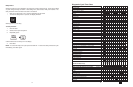
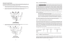
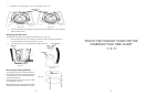
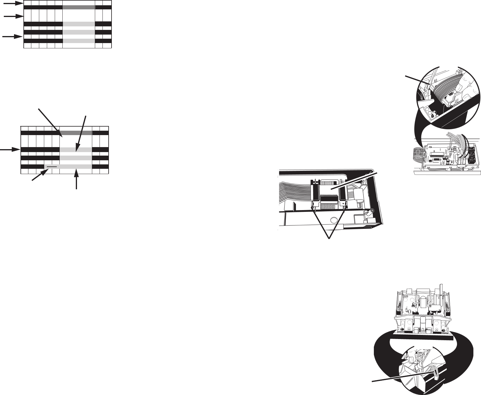
There are 45 intervals in the Common Cycle Time
Chart. Not all intervals have the same time as-
signments from cycle to cycle. An interval may
be only seconds long or up to 20 minutes in length.
More than one function can take place during an
interval. The LED display, if present, will show
the time remaining in the cycle.
(Fig. 4-2)
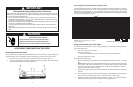
Thermal Hold intervals do not show specific time
lengths. The length of these intervals is deter-
mined by input from the thermistor.
(Fig. 4-3)
If
the thermal cap temperature is not reached in a
predetermined length of time, the electronic con-
trol will proceed to the next interval. (See Note 3,
page 33.)
In the same row as the Cycle Name, the shaded
or solid bars indicate all possible intervals that
may be used in that cycle. All clear intervals are
never used. In cycle variation intervals, black bars
indicate intervals always used. Gray bars with
arrows indicate intervals that are skipped in one
or more variations of a cycle. Shaded bars with-
out arrows indicate that the heater may or may
not be invoked during thermal holds. (NOTE:
During APF and drain functions the heater is
turned off. This is a UL requirement and is built
into the electronic control programming. See Note
2, page 33)
1:35
0:05
0:05
4:00
2:00
1:00
1:00
45 44 43 42 41 40 39 38
[99]
[99]
[98]
[98
[98] [98] 94 92 92 91
[98] [98] 94 92 92 91
[99] [98 [98] [98] 86 84 84 83
Intervals
Always Used
Fig. 4-3
Intervals that
are skipped
>
THERMAL HOLD
Thermal Cap
Temperature
[135F / 57C]
[135F / 57C]
[135F / 57C]
Cycle Minutes
Remaining
When Thermal Hold
is Initiated
Thermal Hold
Intervals do not have
specified time length
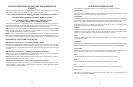
Quick Clean/Time Saver Cycle
The Quick Clean/Timer Saver cycle has a unique variation. During the initial water fill, the thermistor
in the sump monitors the incoming water temperature. If it is 135° F (57° C) or above the electronic
control will skip intervals 39 through 36. This shortens the wash/rinse time by eliminating a drain and
fill sequence (See Note 1b and 1c, page 32).
1:35
0:05
0:05
4:00
2:00
1:00
1:00
45 44 43 42 41 40 39 38
[99]
[99]
[98]
[98]
[98] [98] 94 92 92 91
[98] [98] 94 92 92 91
[99] [98] [98] [98] 86 84 84 83
Intervals
Length of
Interval
Fig. 4-2
Time
Remaining
in
Display
THERMAL HOLD
[135F / 57C]
[135F / 57C]
[135F / 57C]
Bracketed number indicate Spinning
Clock until cycle variation is
determined.