


2916
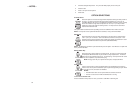
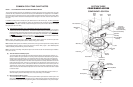
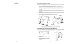
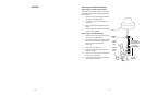
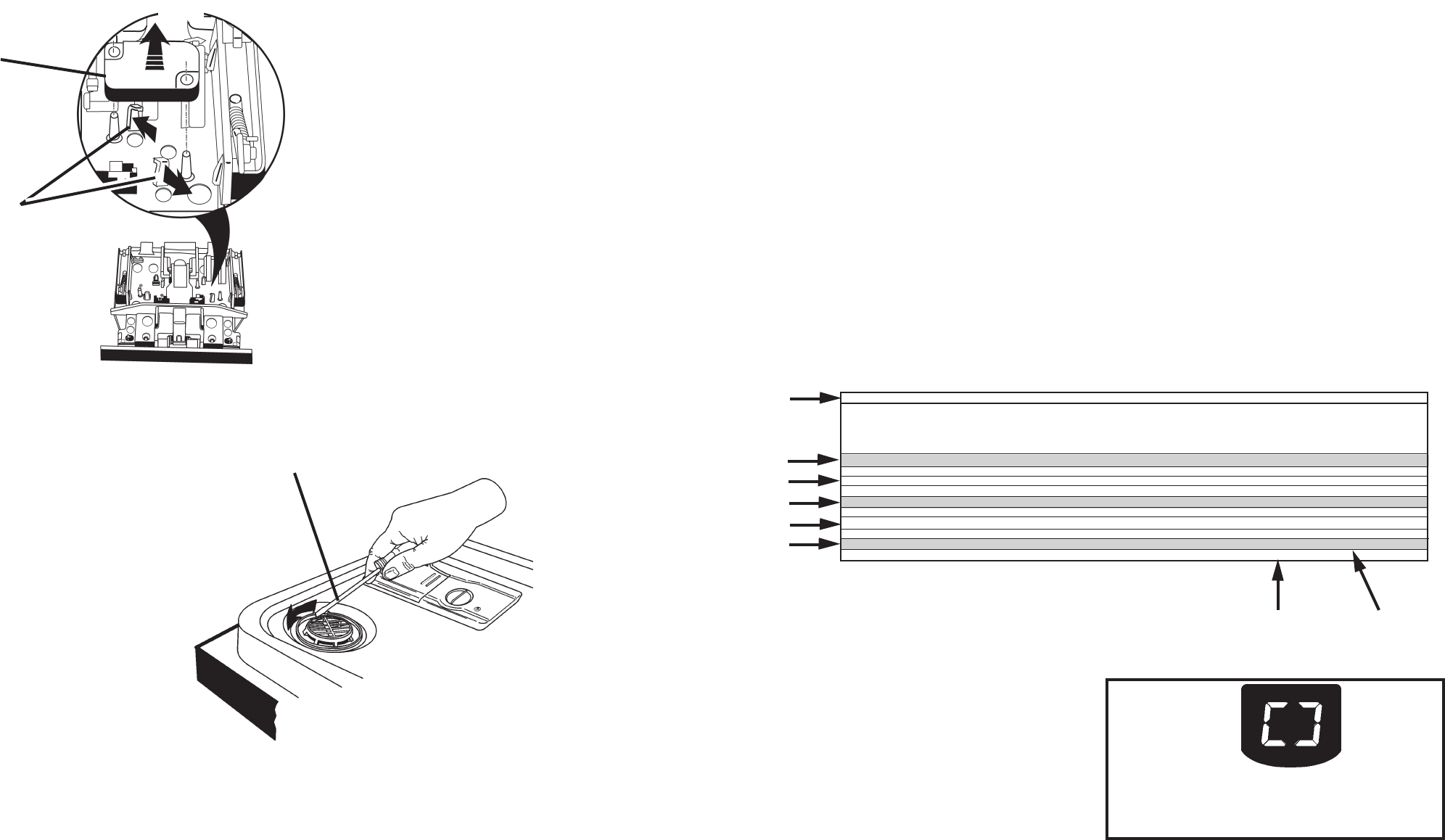
Removing the Active Vent
Assembly
The Active Vent Assembly is located in the con-
sole area.
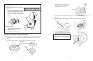
1. Remove the six (6) screws securing the
control panel to the door frame.
2. Disconnect the wiring harness connectors
from the wax motor terminals on the ac-
tive vent assembly.
3. Loosen, but do not remove the four T-15
Torx screws securing the left side of the
outer door panel to the door frame. This
will provide addition room to easily remove
the active vent assembly.
4. Using a flat bladed screwdriver in the slot
provided at the bottom of the interior vent
grille, turn the vent grille counterclockwise
¼ turn and remove the grille.
(Fig. 3-6)
5. The active vent assembly will drop free of
the dishwasher door.
Fig. 3-6
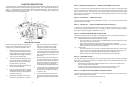
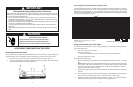
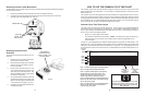
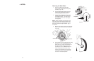
Removing the Door Latch Microswitch
The Microswitch will be located on either the right or left side of the door latch assembly depending on
the control panel version.
1. Disconnect the wiring harness connectors from the microswitch terminals.
2. Pull back on the two (2) plastic retaining tabs securing the microswitch to the door latch
assembly and lift the microswitch out.
(Fig. 3-5)
Fig. 3-5
Inset
Lift Microswitch
Spread Tabs
(Caution: These
tabs can break.)
Use Flat Bladed
Screwdriver and Turn
interior Vent Grille ¼ Turn
Counter-clockwise
NORMAL NOTES 1A,9,14B,15,16
INTERVAL TIME (min:sec)
HIGH SOIL WITH P.SCOUR / H.T.SCRUB OPTION [Soil sensed in Interval 42] NOTE 14B 95:00 w/o Th.Holds
NUMERIC DISPLAY CYCLE TIME (spinning “CLOCK” pattern in INTERVALS 45-42 for some models, see NOTE 5)
HIGH SOIL [Soil sensed in Interval 42] NOTE 1A 95:00 w/o Th.Holds
NUMERIC DISPLAY CYCLE TIME (spinning “CLOCK” pattern in INTERVALS 45-42 for some models, see NOTE 5)
LOW SOIL (or Non-Sensor Model) H.T.SCRUB OPTION [No soil sensed in Interval 42] NOTE 14B 87:25 w/o Th.Holds
NUMERIC DISPLAY CYCLE TIME (spinning “CLOCK” pattern in INTERVALS 45-42 for some models, see NOTE 5)
LOW SOIL (or Non-Sensor Model) [No soil sensed in Interval 42] NOTE 1A 87:25 w/o Th.Holds
NUMERIC DISPLAY CYCLE TIME (spinning “CLOCK” pattern in INTERVALS 45-42 for some models, see NOTE 5)
LOW SOIL (or Non-Sensor Model) [No soil sensed in Interval 42] — E. STAR MODEL NOTE 1A 78:20 w/o Th.Holds
NUMERIC DISPLAY CYCLE TIME (spinning “CLOCK” pattern in INTERVALS 45-42 for some models, see NOTE 5)
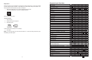
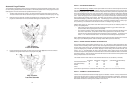
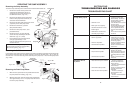
HOW TO USE THE COMMON CYCLE TIME CHART
The Common Cycle Time Chart reproduced on page 27 of this Job Aid can be found on the Tech
Sheet supplied with each dishwasher. The Tech Sheet is located behind the access panel at the
bottom of the unit.
The Common Cycle Time Chart appears to be more complex than a typical Esterline Chart. This is a
result of the greatly expanded number of cycles and cycle variations possible with electronic controls
as opposed to previous electro-mechanical controls. The chart reflects all possible cycles/cycle varia-
tions available on ALL Year 2000 Stainless Steel Dishwasher models. As a result the chart may list
some cycles that will not apply to the specific model being serviced.
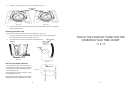
Common Cycle Time Chart Layout
The wash cycles are listed on the left side of the chart. Cycle names such as Anti-Bacterial/Baked-
On-Cookware may be designated as Anti-Bacterial on some models and Baked-On-Cookware on
others. Cycle variations are listed directly underneath each cycle name. These variations are depen-
dent on one or more of the following factors:
• What, if any, wash options were chosen?
• The Soil Sensor detected soil in the water. (NOTE: If the Soil Sensor does not trip during a
particular cycle, the unit uses the same variation of the cycle that is applicable for non-
sensor models.)
In Figure 4-1, gray highlighted cycle variations indicate options the customer can select (Notes 1 & 3,
pages 32 & 33). The gray highlighted cycle variation Low Soil - ENERGY STAR is an exception and
indicates a unique default cycle for these models (Note 1a, page 32). The unhighlighted cycle varia-
tions are based on input from the soil sensor or are defaults based on specific models (Notes 2 & 4,
page 33).
Cycle
Name
Notes further
explain
Cycle/Variation
Function
Cycle Duration
NOT
Including
Thermal Holds
Fig. 4-1
Note 1
Note 2
Note 3
Note 4
Note 5
Note 1 - Customer Selected Option, High Soils Sensed
Note 2 - No Option Selected, High Soils Sensed
Note 3 - Customer Selected Option, Cycle Adjusted/
Shortened because no soils were sensed. (This
variation only applies to the normal cycle.) Cycle
variation may be same as Non-Sensor models.
Note 4 - No Option Selected, Cycle Adjusted/Shortened
because no soils were sensed. Cycle variation may be
same as Non-Sensor models.
Note 5 - No Option Selected, Cycle Adjusted/Shortened
because no soils were sensed. Cycle variation is
unique to Energy Star models.
During Soil Sensing function (Interval 42), the LED
display will show spinning “CLOCK” pattern. Clock
countdown will begin once the cycle variation has
been determined.