


3114
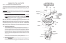
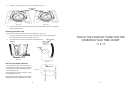
ACCESSING COMPONENTS IN THE DOOR
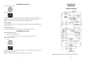
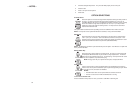
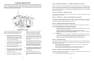
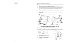
Removing the Console Panel
The control panel on the KitchenAid KUD01 Dishwasher comes in two versions: a) Split Controls: Top
and Front Display and b) Front Display. Both control panels are removed in the same manner.
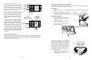
1. Remove the six (6) screws securing the control panel to the door frame.
(Fig. 3-1)
2. The control panel will now drop down and be free of the door assembly. The wiring harness
will remain connected to the console components.
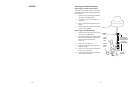
! WARNING
ELECTRICAL SHOCK HAZARD
Disconnect power before servicing the dishwasher.
Replace all panels before operating the dishwasher.
Failure to do so can result in death or electrical shock.
! IMPORTANT
Electrostatic Discharge (ESD) Sensitive Electronics
ESD problems are present everywhere. ESD may damage or weaken the electronic control as-
sembly. The new control assembly may appear to work well after repair is finished, but failure may
occur at a later date due to ESD stress.
• Use an anti-static wrist strap. Connect wrist strap to green ground connection point or un-
painted metal in the appliance. - OR - Touch your finger repeatedly to a green ground connec-
tion point or unpainted metal in the appliance.
• Before removing the part from its package, touch the anti-static bag to a green ground connec-
tion point or unpainted metal in the appliance.
• Avoid touching electronic parts or terminal contacts; handle electronic control assembly by
edges only.
• When repacking failed electronic control assembly in anti-static bag, observe above instruc-
tions.
Fig. 3-1
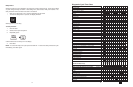
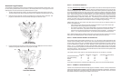
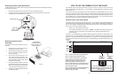
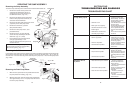
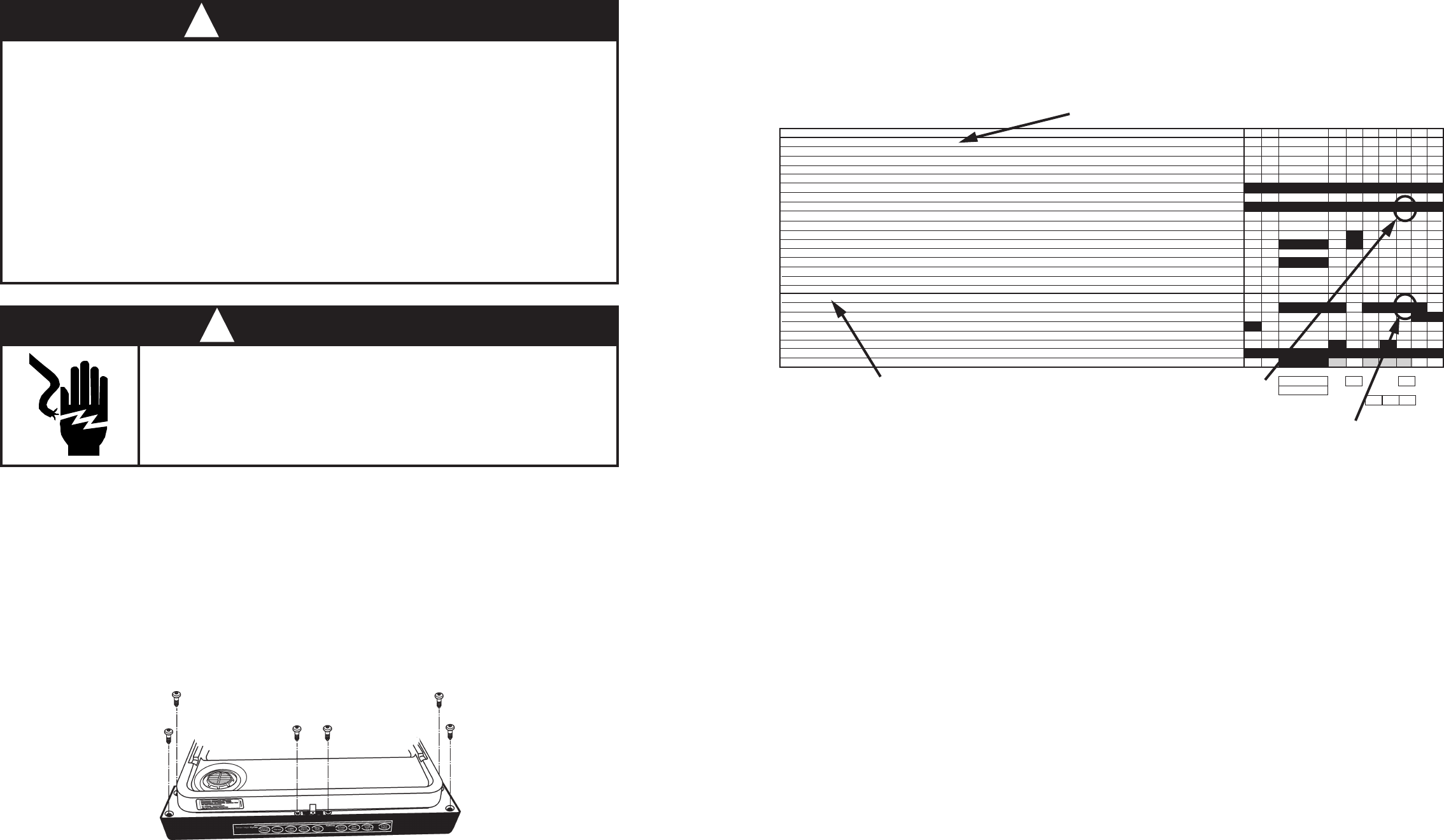
Cycle Progression & Status Indicators-Output Loads
Located in the lower third section of the left column are a listing of cycle Status Indicators (1) signifying
what is happening during a cycle. Some of these indicators are for engineering use only and not
applicable for service diagnosis (†). The output loads (2) are listed at the bottom of the left hand
column. The solid and shaded bars to the right indicate the potential use of cycle indicators and loads
by at least one cycle variation.
(Fig. 4-4)
Wash Motor should be running
“CYCLE PROGRESSION & STATUS INDICATORS
†PROG BAR W1
†PROG BAR W2
WASHING (PROG BAR W3)
†PROG BAR R1
†CIRC (PROG BAR R2) (This LED will be labeled as ‘WASHING’ on models that use it, but it is on during all Wash and Rinse Periods)
RINSING
DRYING
SOAKING NOTE 7
SOAKING/SENSING NOTE 7
ADD-A-DISH
WATER HEATING (THERMAL HOLD INDICATOR) NOTE 6
SANITIZED NOTE 8,15
CLEAN NOTE 8
OUTPUT LOADS
WASH MOTOR (MAIN WINDING)
DRAIN MOTOR NOTE 2
FILL NOTE 2
APF ENABLED INTERVALS -Max # of APF Purges allowed in Interval NOTE 2
DETERGENT / RINSE AID DISPENSER
VENT
HEATER NOTES 4,10,11,16
17 16 15 14 13 12 11 10 9 8
3
15
94
11
11 11
Rinsing Indicator should be lit
Fig. 4-4
(2)
(1)
† NOTE: These cycle progressions are not used
for service diagnosis.
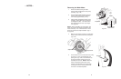
Using the Common Cycle Time Chart
To confirm the correct operation of a cycle or properly diagnose a malfunction, the following informa-
tion must be determined:
• Does the model have a Soil Sensor?
• What cycle was chosen?
— If Quick Cleanup cycle was chosen, what was the first fill water temperature?
• What Cycle Option was chosen?
Proceed with the following steps:
1. Start the selected cycle and program the unit for Rapid Advance service feature. (See page
36).
NOTE: Most likely the cycle that is selected will change to the “Low Soil” variation because of
low soil levels. Also, APF events will not occur. to check the APF function, the harness leads
to the soil sensor will need to be shorted together. Shoring these lwads tells the electronic
control that “High Soil” levels are present.
2. Advance through the intervals to the one that will operate the load or perform the function to be
checked.
3. If the load does not operate, refer to the wiring diagram or applicable strip circuit to determine
what connections and components to check. (See Section Five - TECH TIPS.)
4. Whenever possible, check components for resistance or continuity. On components where
resistance or continuity checks are not reliable, conduct voltage checks.