


10
Check Your Chimney
Chimney must be clean, right size, properly constructed
and in GOOD CONDITION.
1.
Installation must conform to requirements of the
authority having jurisdiction or, in absence of such
requirements, to the National Fuel Gas Code, ANSI
Z223.1/NFPA 54 or of the Natural Gas and Propane
Installation Code, CAN/CSA B149.1, or applicable
provisions of the local building codes..
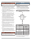
2.
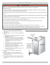
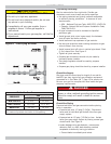
Boiler’s induced draft blower has 3” outlet. 3” X
4” increaser fi tting is included in parts bag. Locate
increaser fi tting on outlet of induced draft blower, and
secure gas-tight with bead of furnished silicone sealant.
Increaser fi tting is required on this boiler for Category I
venting, and 4” is minimum permissible vent diameter.
This does not imply vent connector is intended to be 4”
diameter pipe. Vent connector shall be sized according
to appropriate venting tables in the National Fuel
Gas Code and may be required to be larger than 4”
diameter.
NOTICE
Boiler installation for chimney venting is not complete
unless increaser fi tting is located and secured.
3.
These are high effi ciency boilers with low stack or
exhaust temperature.
4.
Venting into masonry chimney without liner, line
chimney from top to bottom with either:
A. Listed Type B vent pipe
B. Listed fl exible vent liner
C. Poured ceramic liner.
5.
Outside chimneys should not be used unless they are
(choose one of the following):
A. Enclosed in a chase
B. Lined with Type B vent pipe
C. Use listed fl exible vent liner
D. Use certifi ed chimney lining system
6.
Vent connector from boiler to chimney should run as
directly as possible with as few elbows as possible.
7.
Where possible, it is recommended to common vent
water heater and boiler. Consult appropriate Vent
Sizing Tables in National Fuel Gas Code for specifi c
requirements of multiple appliance venting.
8.
Boiler is only appliance connected to vent, Type B vent
pipe is recommended for vent connector.
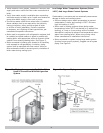
9.
Slope pipe up from boiler to chimney not less than 1/4”
per foot (21mm/m).
10.
End of vent pipe must be fl ush with inside face of
chimney fl ue. Use sealed-in thimble for chimney
connection.
11.
Fasten sections of vent pipe with sheet metal screws to
make piping rigid. Use stovepipe wires to support pipe
from above.
12.
Do not connect to fi replace fl ue.
13.
Do not install damper on this boiler.
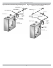
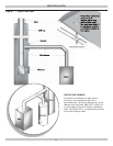
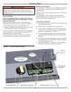
Minimum Vent Pipe Clearance
• Use Type B vent pipe through crawl space. Where vent
pipe passes through combustible wall or partition, use
ventilated metal thimble. Thimble should be 4 inches
larger in diameter than vent pipe.
• Boiler installed with single wall vent, must have 6”
clearance between its surface and any combustible
material. New Type B gas vent or fl exible liner must be
installed in accordance with instructions furnished with
vent. Maintain clearances as specifi ed for vent pipe.
• Verify vent pipe is fi re-stopped where it goes through
fl oor or ceiling. It should have approved vent cap with
clearances from roof. If clearances are less than shown
in have vent checked by local authorities. See Figure 7,
Page 11.
• Vent connectors serving appliances vented by natural
draft shall not be connected into any portion of
mechanical draft systems operating under positive
pressure.
VENT INSTALLATION