


7
1.
Refer to local codes and appropriate ASME Boiler
and Pressure Vessel Code for additional installation
requirements.
2.
Install relief valve on 3/4” pipe nipple in tapped boiler
opening.
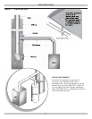
A. Pipe discharge line following guidelines in preceding
Warning. See Figure 2.
B. Discharge line pipe size shall be equal or greater
than that of relief valve outlet over entire length
of discharge line with no intervening shutoff valve
between safety relief valve and discharge to
atmosphere.
C. Discharge line shall terminate with plain end to
atmosphere where any discharge will be clearly
visible and is at no risk of freezing.
D. Discharge line shall be independently supported to
avoid applied stress on relief valve.
E. Installation shall allow complete drainage of relief
valve and discharge line.
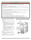
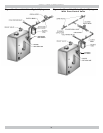
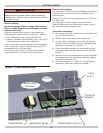
3.
Install Drain Valve on lower left side of boiler as
marked.
4.
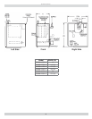
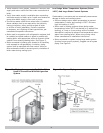
Install Temperature and Pressure Gauge into ¼”
bushing threaded in tee furnished with supply piping.
See
Figures 3 and 4
.
5.
Connect Supply and Return Lines to boiler. Figure 3 &
4. Connections may require certain additional fi ttings
and parts.
INSTALLATION SYSTEM PIPING
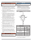
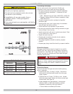
WARNING
Burn or Scald Hazard. Discharge line shall be installed to relief valve outlet connection to avoid burns,
scalding, or water damage due to discharge of steam and/or hot water during operation.
Discharge line shall:
• connect to relief valve outlet and piped down to safe point of disposal. Check local codes for maximum
distance from fl oor or allowable safe point of discharge.
• be of pipe size equal to or greater than that of the relief valve outlet over the entire length of discharge
line;
• have no intervening shutoff valve between safety relief valve and discharge to atmosphere (do not plug or
place any obstruction in discharge line.
• terminate freely to atmosphere where any discharge will be clearly visible and at no risk of freezing;
• allow complete drainage of the valve and the discharge line;
• be independently supported and securely anchored to avoid applied stress on the relief valve;
• be as short and straight as possible;
• terminate with plain end (not threaded);
• be constructed of material suitable for exposure to temperatures of 375° F; or greater.
Refer to local codes and appropriate ANSI/ASME Boiler and Pressure Vessel Code, Section IV, or Boiler,
Pressure Vessel and Pressure Piping Code, CSA B51 for additional installation requirements.
!
Check local codes
for maximum
distance from
fl oor or other
allowable safe
point of discharge
RELIEF VALVE
DISCHARGE
PIPING
Figure 2 - Safety Relief Valve Discharge Piping