


27
APPENDIX A - CONTROL MODULE
A.1 Installation Environment Considerations
WARNING
If you do not follow these instructions
exactly, a fi re or explosion may result
causing property damage, personal injury
or loss of life.
• Do not use this appliance if any part has
been under water. Immediately call a qualifi ed
service technician to inspect appliance and to
replace any part of control system and any gas
control which has been under water.
• Do not allow water to drip on controls. Prevent
condensation by allowing air circulation around
module and gas control.
• Do not use corrosive chemicals around or on
module or gas control.
!
• Install plastic cover.
• Controls can be damaged by excessively high
temperatures. Verify adequate air circulation around
louvers is maintained when installing boiler.
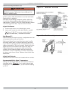
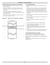
A.2 Electrical Connections
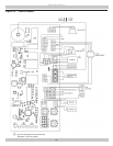
Connect Module Connectors Figure 10, Page 18
• L1& L2 leads inside J box using wire nuts. Secure J
box cover.
• Circulator harness to circulator. Harness comes
plugged into module with Molex
®
plug.
• Thermostat connection to yellow wires marked TT
using wire nuts.
• Ensure remaining Molex
®
plug connectors have not
worked loose during transit.
• Check sensing bulb is fully inserted in well and is not
loose.
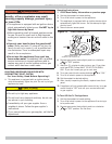
A.3 Adjusting Settings
To discourage unauthorized changing of settings, procedure
to enter adjustment mode is required.
To enter adjustment mode, press UP, DOWN, and I buttons
(see Figure 1) simultaneously for three seconds. Press and
release I button until parameter requiring adjustment is
displayed:
о “SP_” Setpoint (180 °F default setting; adjustable
between 130 and 220 °F)
о “Df_” Setpoint Differential (15 °F default setting;
adjustable between 10 and 30 °F)
о “°F_” Degrees Fahrenheit
Press UP or DOWN button until parameter has reached
desired value. After 60 seconds without any button inputs,
control automatically returns to READ mode.
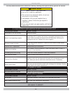
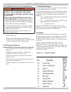
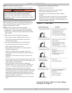
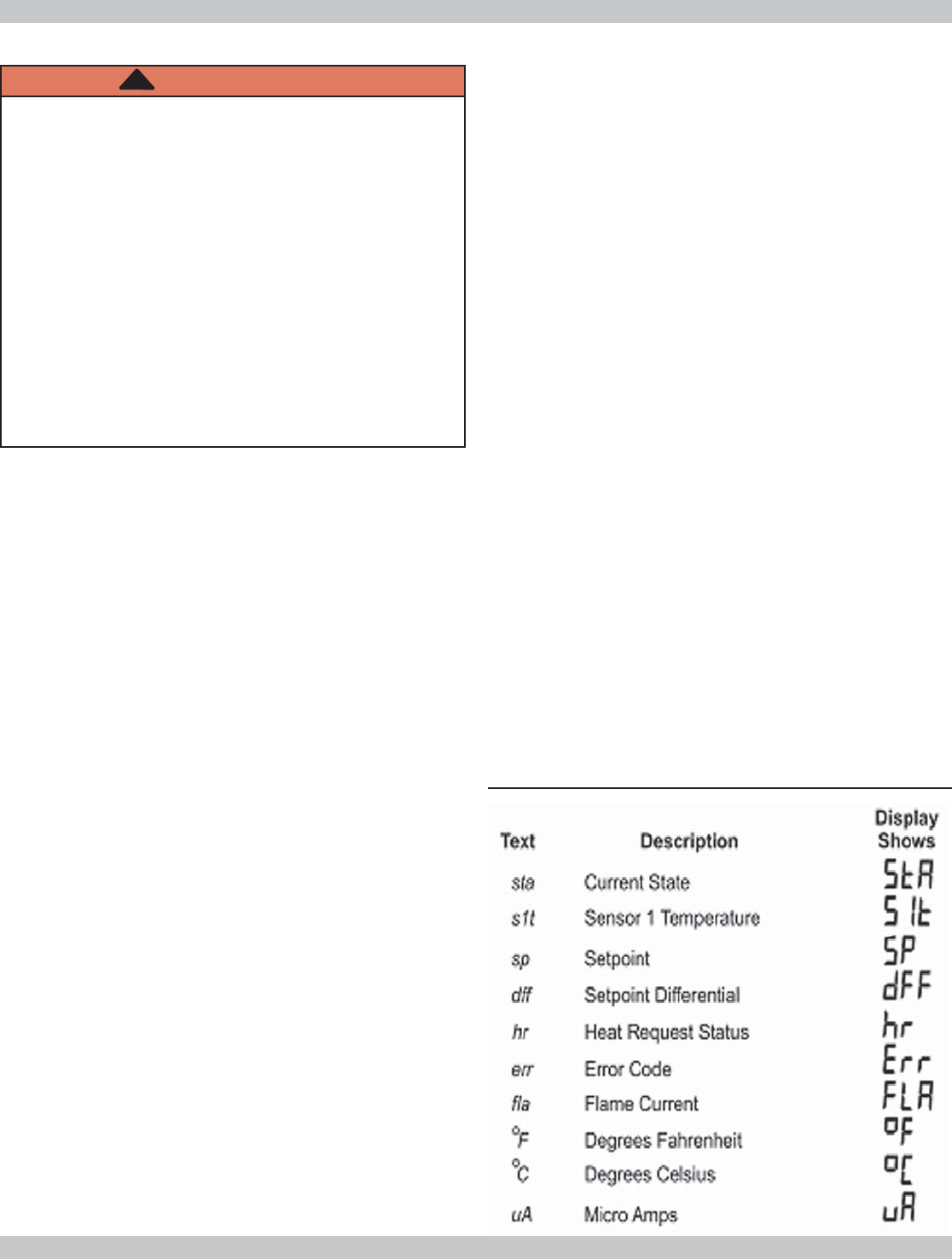
A.4 Display
In RUN mode, status items and parameters are viewable.
Example, to display setpoint, control fl ashes “sp” (setpoint)
followed by temperature (i.e., 135), followed by °F or °C.
To read settings, press and release I key to fi nd parameter
of interest.
Example, press and release I until setpoint (sp) is
displayed, followed by three-digit number, i.e., 190,
followed by °F or °C. Press I button again will display (S1T)
Sensor 1 Temperature followed by three-digit number and
corresponding degree designator.
See Display Readout.
Figure 15 - Display Readout