


30
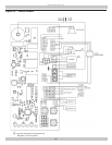
APPENDIX A - CONTROL MODULE
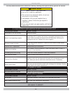
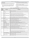
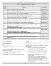
Table 2 - Troubleshooting Error Codes
Error
Code
Number
Defi nition Consequence
2
Pressure switch failed to open (stuck closed).
Wait for recovery
4 Flame current too low. Check for fl ame. Non critical alarm
6
Flame sensed out of normal sequence (before opening or after closing gas valve).
Soft lockout
18 Gas valve relays welded. Five consecutive soft lockouts. Hard lockout
23
Flame sensed during prepurge ( before gas valve signaled opened).
Soft lockout
24 Flame sensed during postpurge (after gas valve signaled closed). Soft lockout
29
Pressure switch failed to close (Contacts stuck open)
Wait for recovery
32
Sensor 1 error. Temperature sensor in well is not reading correctly.
Verify it is connected to board. Replace if necessary.
Wait for recovery
57
Igniter fl ame rod shorted to burner ground
Wait for recovery
58 Igniter fl ame rod shorted to burner ground. Repair or replace igniter. Wait for recovery
59 Line Voltage error - voltage out of specifi cation high or low (15-37V (44-66Hz)) Wait for recovery
60
Applies only to thermostats having on-board transformer.
Polarity is wrong in this case.
Wait for recovery
Thermostat input higher than threshold.
61
Line voltage unstable - possibly too may heavy loads switching on and off causing
erratic supply voltage.
Wait for recovery
62
Soft lockout: maximum number of retries exceeded.
Soft lockout
Soft lockout is reset after one hour if alarm reason disappears.
63 Soft lockout: maximum number of recycles exceeded. Soft lockout
64 Soft Lockout - electronics failure. On-board self diagnostics detected error. Soft lockout
65
Over temperature error. Sensor measured temperature in excess of maximum
allowable limit.
Soft lockout
Note: Soft lockout time is 1 hour or manual reset. Hard lockout requires manual reset.
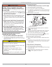
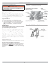
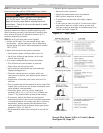
A.9 Intermittent Pilot
Ignition System Checks
STEP 1: Check ignition cable.
• Verify ignition cable does not run in contact with metal
surfaces.
• Verify only factory supplied Ignition cable (or approved
replacement) is used.
• Verify connections to ignition module and igniter or
igniter-sensor are clean and tight.
• Verify ignition cable provides good electrical continuity.
STEP 2:
Verify ignition system grounding. Nuisance shutdowns are
often caused poor or erratic grounding.
Common ground is required for module and pilot burner/
igniter sensor.
— Check for good metal-to-metal contact between
pilot burner bracket and the main burner.
— Check ground lead from GND (BURNER) terminal
on module to pilot burner. Verify connections are
clean and tight. If wire is damaged or deteriorated,
replace with No. 14-18 gauge, moisture-resistant,
thermoplastic insulated wire with 105°C [221°F]
minimum rating.
— Check ceramic fl ame rod insulator for cracks or
evidence of exposure to extreme heat, which can
permit leakage to ground. Replace pilot burner/igniter
sensor and provide shield if necessary.
— If fl ame rod or bracket is bent out of position, restore
to correct position.