


13
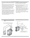
OPTIONAL HORIZONTAL VENTING INSTRUCTION
Horizontal venting with a power venter is an alternate
method of sidewall venting. This boiler is CSA listed for
sidewall venting with standard single wall galvanized or
Type B vent pipe when using the following power venter
kits, which were specifi cally sized for these boilers:
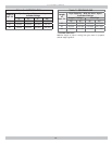
Table 4- Field Controls
Number Of
Boiler Sections
Field Controls
Power Venter
2, 3, 4, 5 SWG-4D
6, 7 SWG-5D
Some possible reasons for using a power venter for
sidewall venting:
1.
May be preferred by local codes.
2.
Need a vent piping run beyond 30’ (9.1m) (but not
more than 50’ (15.2m)).
3.
The boiler installation site experiences gusting or high
winds. A power venter can help prevent the boiler from
short cycling due to gusting or high winds by providing
vent exhaust pressures greater than the boiler’s
induced draft blower alone.
4.
When installers or homeowners prefer a negative
pressure vent system instead of a positive pressure
vent system.
5.
May be more cost effective than stainless steel
venting, particularly at longer vent length.
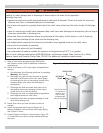
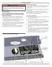
The Field Controls power vent kit includes either a
SWG-II-4HD or SWG-II-5 power venter, a MG-1 4”
barometric draft controller, and the CK-43D controls kit.
Confi rm that installing a power venter is an option allowed
by local codes. Follow the specifi c power venter installation
instructions issued with the power venter kits. Although
the power venter is equipped with its own fan, the fan on
the boiler remains in place and is unaltered when a power
venter is used.
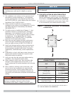
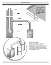
When sidewall venting, fl ue gases must be vented to a
point in relation to the prevailing wind so that they may
freely disperse without being blown back at the building
causing discoloration, or into the building through doors or
windows causing odors. Also, under certain conditions fl ue
gases will condense, forming moisture. In such cases, steps
should be taken to prevent building materials at the vent
terminal from being damaged by the exhausted fl ue gas.
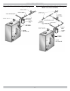
When installing single wall galvanized vent pipe for power
venting follow the specifi c power venter installation
instructions for layout, location of the barometric draft
control and termination connections.
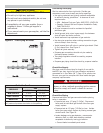
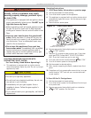
When joining and sealing the single wall galvanized or Type
B vent piping, use RTV silicone sealant with a minimum
temperature rating of 400°F. For 3” vent pipe runs, be-
gin with the female end of the vent pipe over the boiler’s
induced draft blower outlet. For 4” vent pipe runs begin
with the galvanized 3” to 4” increaser fi tting (included in
the boiler’s parts bag) over the induced draft blower outlet.
Then follow by placing the female end of the 4” vent pipe
over the increaser fi tting.
When joining pieces of single wall galvanized vent pipe, a
substantial bead of silicone should be used at the joint to
insure a leak proof connection.