


16
ELECTRICAL WIRING
Electrical Wiring
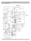
See wiring diagram Figure 10 page 18 for details.
Refer to Ladder Diagram from document envelope
received with boiler.
Electrically bond boiler to ground in accordance with
requirements of authority having jurisdiction. Refer to:
• USA- National Electrical Code, ANSI/NFPA 70.
• Canada - Canadian Electrical Code, Part I, CSA C22.1:
Safety Standard for Electrical Installations.
If any of the original wire as supplied with this appliance
must be replaced, it must be replaced with type 105°C
thermoplastic wire or its equivalent
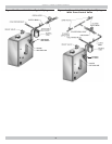
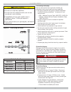
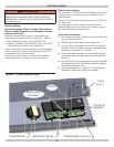
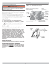
Circulator harness is factory wired to control module.
Connect harness to circulator in fi eld. See Figure 9.
WARNING
Electrical shock hazard. Turn OFF electrical power
supply at service panel before making electrical
connections. Failure to do so could result in death
or serious injury.
!
Thermostat Installation
1.
Thermostat should be installed on an inside wall about
four feet above the fl oor.
2.
NEVER install a thermostat on an outside wall.
3.
Do not install a thermostat where it will be affected
by drafts, hot or cold pipes, sunlight, lighting fi xtures,
televisions, a fi replace, or a chimney.
4.
Check thermostat operation by raising and lowering
thermostat setting as required to start and stop the
burners.
5.
Instructions for the fi nal adjustment of the thermostat
are packaged with the thermostat (adjusting heating
anticipator, calibration, etc.)
6.
Set heat anticipator at .2 amps. 24 volt thermostat
connects to yellow low voltage wires labled T.
Electric Power Supply
Run a separate 115 volt circuit from separate over current
protective device 15 ampere circuit in electrical service
entrance panel.
Connect 115 volt power supply to terminals L1 (HOT) and
L2 inside J box.
Run 14 gauge or heavier copper wire from boiler to
grounded connection in service panel or properly driven
and electrically grounded ground rod.
J BOX
L1 & L2
TRANSFORMER THERMOSTAT WIRES
R
R
TH
E
L
CIRCULATOR
HARNESS
CI
CI
CI
C
C
H
H
H
H
TRANSFORMER LINE VOLT
E
R LINE V
O
L
T
T
T
BLOWER
TRANSFORMER
SECONDARY
Figure 9 - Control Module Panel