


5
INSTALLATION PROCEDURE
WARNING
Improper installation, adjustment, alteration, service
or maintenance could result in death or serious
injury
.
!
1.
The installation must conform to the requirements of
the authority having jurisdiction or, in the absence
of such requirements, to the National Fuel Gas Code,
ANSI Z223.1/NFPA 54, and/or Natural Gas and Propane
Installation Code, CAN/CSA B149.1
2.
Where required by authority having jurisdiction,
installation must conform to the Standard for Controls
and Safety Devices for Automatically fi red Boilers,
ANSI/ASME CSD-1.
3.
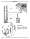
This boiler series is classifi ed as a Category I. Vent
installation shall be in accordance with “Venting of
Equipment ,” of the National Fuel Gas Code, ANSI
Z223.1/NFPA 54, or “Venting Systems and Air Supply
for Appliances,” of the Natural Gas and Propane
Installation Code, CAN/CSA B149.1, or applicable
provisions of the local building codes.
4.
Boiler has met safe lighting and other performance
criteria with gas manifold and control assembly on
boiler per latest revision of ANSI Z21.13/CGA 4.9.
5.
Install such that gas ignition system components are
protected from water (dripping, spraying, rain, etc.)
during appliance operation and service, (circulator
replacement, condensate trap, control replacement,
etc.).
6.
Locate boiler on level, solid base as near chimney as
possible and centrally located with respect to heat
distribution system as practical.
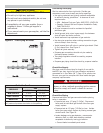
7.
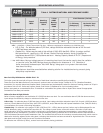
Verify you have the right size boiler before starting
installation. See rating and capacity table.
8.
When installed in utility room, door should be wide
enough to allow largest boiler part to enter, or to
permit replacement of another appliance such as water
heater.
9.
Boiler installed in building under construction, take
care to insure clean combustion air supply during
construction process. Airborne particulates such as
from drywall dust and from fi berglass insulation can
clog burner ports and cause incomplete combustion and
sooting.
NOTICE
Follow local regulations with respect to installation
of CO detectors.
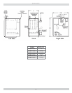
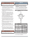
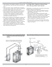
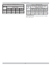
Table 2 - BOILER MINIMUM CLEARANCE TO
COMBUSTIBLES
Unit
Minimum
Clearances
Top 6” (152mm)
Rear 6” (152mm)
Control Side 8” (203mm)
Opposite Side 6” (152mm)
Front (Alcove) 18” (457mm)
Flue/Vent Connector 6” (152mm)
Near Boiler Piping 1/2” (13mm)
Set unit on concrete or other noncombustible material base or
fl oor. DO NOT INSTALL ON CARPETING.
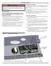
Figure 1 - Minimum Clearances To Combustible
Construction
10.
FOR INSTALLATION ON NON-COMBUSTIBLE
FLOORS ONLY - For installation on combustible
fl ooring special base must be used. (See Replacement
Parts Section.) Do Not Install Boiler on carpeting.
11.
Verify boiler is supplied with correct type of gas, fresh
air for combustion, and suitable electrical supply.
WARNING
Fire hazard. Do not install boiler on combustible
fl ooring or carpeting. Failure to follow these
instructions could result in death or serious injury.
!
8”
Boiler
Rear
Front
Control Side
Opposite Side
18”
6”
6”
8”