


10
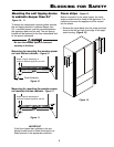
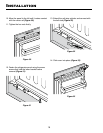
Icemaker
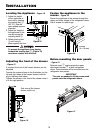
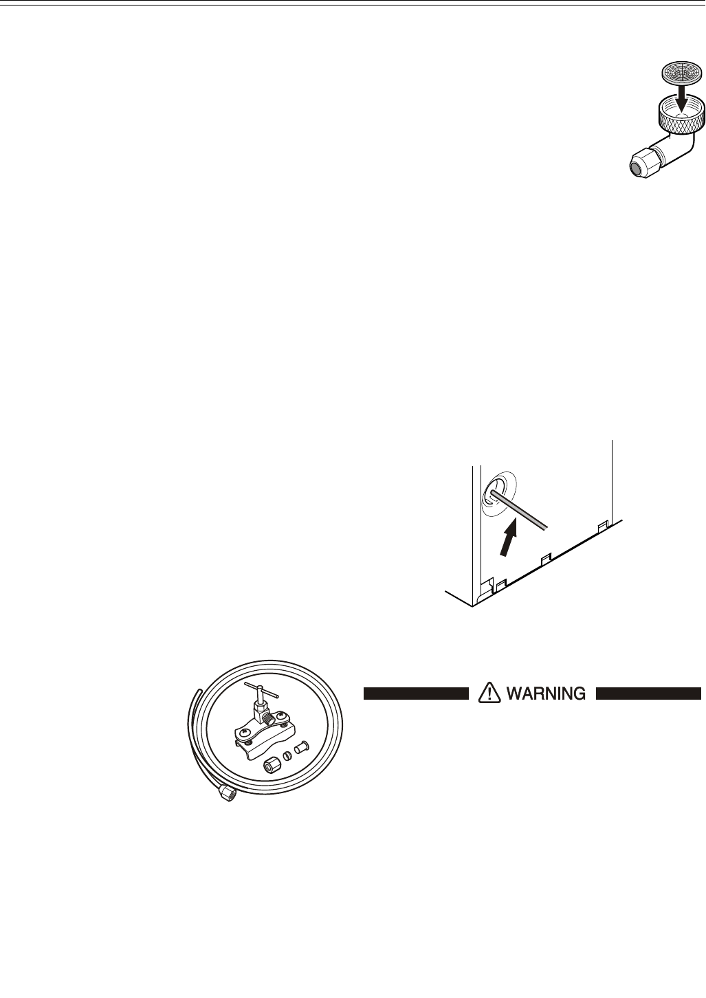
Figure 14
• Thesolenoidvalvehasametric
R3/4 male connector. A R3/4
(metric) to a 1/4" OD adapter is
supplied with the ice maker.
• Insertthewaterstrainerprovided
into the OD adapter with the cavity
downwards.
IMPORTANT
Be sure the strainer is inserted with the cavity
downwards. Otherwise the strainer could be
damaged when mounting the OD adapter
onto the solenoid valve.
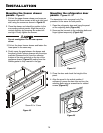
Connection to the Water Supply
1. Move the appliance towards the final position
and leave enough space to work behind.
2. Insert the water supply line into it's intended
opening at the back of the appliance (Figure 14).
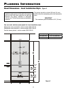
IceMaker
The icemaker for the combined refrigerator-freezer
is located in the freezer compartment. These
instructions only refer to the installation of the ice-
maker. Please refer to the Use and Care Manual
provided with the appliance for operation instruc-
tions. The combined refrigerator-freezer must be
level for the icemaker to function properly.
Safety Instructions and Warnings
• Donotinstallthewaterconnectionwhilethe
combined refrigerator-freezer is connected to an
electrical outlet.
• Theconnectiontothewatersupplymayonlybe
made by a trained and licensed plumber.
• Thewaterqualitymustcomplywiththedrink-
ing water regulations for the geographical area
where the appliance is located.
• Allequipmentanddevicesusedtosupplythe
water to the appliance must comply with the cur-
rent regulations for your geographical area.
Water Connection
• Thewatersupplypressurerequirementsare
different based on whether or not the supplied
Liebherr water filter is installed. With the filter
installed, the pressure must be in the range
of 40-90 psi (2.8-6.2 bar). Without the filter
installed the acceptable pressure range is 22-87
psi (1.5-6 bar). Failure to meet these require-
ments will likely result in ice maker malfunction
and possibly cause a water leakage that can
damage flooring and surrounding furniture.
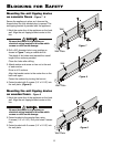
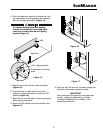
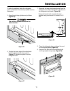
• Usea1/4"ODcopper
line to connect the water
supply to the solenoid
valve. This is not sup-
plied with the refrig-
erator (Figure 13).
• Ashut-offvalve,such
as the saddle valve
illustrated here, must
be installed between
the hose line and the
main water supply so the water supply can be
stopped if necessary.
Do not install the shut-off valve behind the
refrigeration unit.
Figure 13
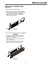
3. Move the power supply line to the area of the
electrical outlet.
Do not connect to the electrical outlet
before the installation is completed and
the water line is connected to the solenoid
valve.