


Installation Section 2
2-12
Part Number 020001552 5/11
Refrigeration Unit Installation
POSITIONING OF REFRIGERATION UNIT
Before proceeding with installation, verify that all
requirements for roof mounted Remote Condenser Units
have been satisfied (if applicable). Refer to the
instructions on installing the Remote Condenser
supplied with the unit.
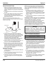
If unit is to rest on floor, locate four 6" (15.2 cm)
adjustable legs (optional). Screw and tighten legs into
the bottom of the refrigeration unit. Set unit in desired
location and adjust legs until unit is level and sturdy. If
unit is to be mounted on stand, position stand and
secure unit to stand. If unit is to be installed on a wall
mount bracket, install wall mount bracket and position
unit on bracket at this time. Fasten unit to bracket with
bolts provided.
EQUIPMENT PLACEMENT
NOTE: All Refrigeration Units must be mounted on
either 6" legs or optional stand.
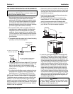
1. Move the stand/refrigeration unit to the designated
area and position it near the wall at a distance of at
least 6" (15.2 cm) for air circulation in air-cooled
units, or at a distance required by local code.
2. Level the stand/unit by adjusting the leg levelers
provide on the legs or stand.
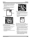
3. If unit is equipped with optional stand, lift the
Refrigeration Unit onto the stand. Position the unit in
the center of the stand. Be sure to orientate the drain
of the refrigeration unit with the drain access hole of
the stand. Secure with 5/8”-11 x 1" bolts supplied in
kit, use two (2) bolts diagonally. Schedule the
plumber and electrician to connect the water supply
and electrical service if you have not already done
so (refer to Electrical Requirements and Plumbing
Requirements for plumbing and electrical
requirements listed in these instructions).
4. Mount any optional equipment at this time. Follow
the installation instructions for each kit required.
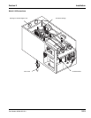
ELECTRICAL CONNECTIONS
NOTE: The electrician must refer to the nameplate and
wiring schematic on the refrigeration unit for correct
electrical requirements. All wiring must comply with all
safety codes. Make sure all refrigeration unit power
switches are in the OFF position.
1. Remove junction box cover.
2. Connect the circuit electrically. (120VAC 30amp circuit)
Refer to chart. Route and connect power supply to
leads in the electrical junction box at the top rear of
the motor compartment.
NOTE: Be sure to connect ground wire(s) to ground
screw located on back panel of junction box.
3. Replace junction box cover.
TOWER INSTALLATION
1. Locate placement of tower on the countertop per
restaurant design. Verify counter has been prepared
to accept the tower via mounting holes. Refer to
tower specs for verification.
2. Mount tower with mounting hardware.
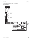
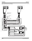
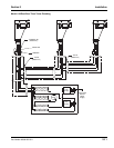
Connect the product lines from the Bag-In-Box or tank.
See the plumbing diagrams for the tower setup that
pertains to your installation.
Connect the product lines either from the bag-in-box or
tank (#1 regular root beer & #2 diet root beer). See the
plumbing diagrams for the tower setup that pertains to
your installation.
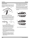
ROUTING INSULATED CONDUIT
1. Before connecting conduit, evaluate store situation and
lay out how the conduit will be routed. Be sure to route
conduit away from traffic areas, moving parts, and heat.
2. Physically route conduit per evaluated plan. Examine
conduit routing and check for neatness, kinks, and
interferences.
CONNECTING INSULATED CONDUIT
NOTE: List what color line was connected to which product
so it can be connected correctly at the towers.
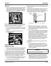
1. Route the conduit to the front opening and into the unit.
Cut the insulation back from the lines inside the water
bath.
!
Caution
Make sure power supply to unit is turned off.