


Section 2 Installation
Part Number 020001552 5/11 2-17
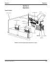
PRE-CHARGED REFRIGERATION LINE REQUIREMENTS
1. Both the discharge and liquid remote condensing lines
must be kept to a minimum distance for maximum
performance. All Multiplex systems are capacity rated to
100 ft (30.5 m) tubing distance between the compressor
and condenser. If you have another brand condenser,
please add additional charge for the condenser (example:
up to three (3) pounds for a MAC condenser).
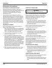
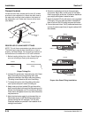
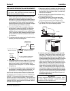
2. Any vertical rise 25 ft (7.62 m) or greater must have a
manufactured or installed trap (bend), in the discharge
refrigeration line from the compressor to the remote
condenser. A trap is necessary for every additional 25 ft
(7.62 m) vertical rise. When excessive vertical rise exists,
this trap allows oil to reach the condenser and return to
the compressor.
3. The easiest method to create a trap is to bend the tubing
(smoothly, no kinks) into the trap form.
4. The trap(s) must be of minimum height of 3" (7.6 cm) and
a width of 6" (15.2 cm) to minimize oil accumulation. The
traps can also be bent out of the refrigeration tubing.
Carefully bend the tubing down 12", and then sweep the
tubing back up.
5. It is critical that the Multiplex remote condensing line size
specifications for the specific model be maintained. The
specifications are 1/2” discharge and 3/8” liquid lines.
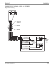
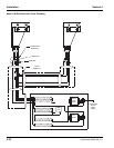
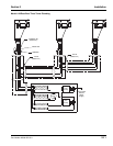
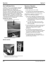
INSTALLING THE MULTIPLEX REMOTE CONDENSER
The Multiplex remote condensing units have a 208-230 Volt,
50/60 HZ, 1 PH fan motor that includes a permanent split
capacitor and internal overload protection. The electrical wires
from the refrigeration unit wire to the condenser. The electrical
installation must be in accordance with local codes, National
Electrical Code and regulations.
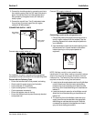
1. Determine a position for installation that will allow access
for maintenance and is free from obstruction. Verify hot air
discharge from other condensers does not interfere with
the inlet of this condenser.
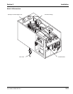
2. Install the four legs to the sides of the condenser using
the mounting bolts provided.
3. The General Contractor or Owner must secure two
treated lumber 4" x 4" x 36" (or longer). You may then
mount the remote condenser to the treated lumber.
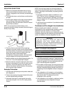
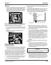
4. The General Contractor or Owner must install a 3" pitch
pot in the roof. Then seal for weather protection.
5. Locate the pre-charged refrigeration lines shipped with
the system. These lines must be a correct length for the
building design. Avoiding any kinks, neatly route these
lines from the remote condenser to the refrigeration unit.
Excess refrigeration tubing must be handled in one of two
ways. When coiling the excess tubing, make sure the
inlet to the coil is at the top of the coil and the exit is the
bottom of the coil. There can be no more than one turn to
the coil. If you have more tubing, you must cut out the
excess before connecting the ends. When cutting the
tubing, you must first evacuate the refrigerant (line sets
have a positive refrigerant holding charge of two to three
ounces). After shortening and welding the tubing together
again, you must vacuum the tubing to 250 microns. Then
recharge the tubing with the appropriate refrigerant at 4
ounces per length of tubing.
Important
If you have a MAC Multi-Pass condenser please add
three (3) pounds additional charge.
Discharge Line
Condenser Trap
To the
Condenser
Discharge Line Trap Every
25 Vertical ft. (7.62 m)
3 ft (.9 m) (minimum) of Discharge
Line Trap at the Compressor
Compressor
3" (7.6 cm) x 6" (15.2 cm)
Maximum Trap Area
!
Caution
Excess refrigeration tubing must be properly cared
for before being connected to either the remote
condenser or the refrigeration unit.
3" Pitch
Roof