


Installation Section 2
2-18
Part Number 020001552 5/11
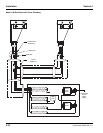
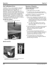
CONNECTING THE PRE-CHARGED
REFRIGERATION LINES
NOTE: Before connecting the pre-charged refrigeration
lines, the refrigeration unit must be properly located,
leveled, and the water bath filled 1" (2.5 cm) below the
installed drain pipe.
1. Attach low side gauge set to service port on each
line set to verify positive pressure within the line set.
NOTE: If for any reason the lines are damaged and/or
leaking or the lines no longer charged, refer to “How To
Re-charge the Line Sets”. If the line set is too long for
the application, refer to “How to Shorten the Line Sets” in
Section 3.
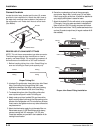
2. Always make the connections at the condenser first,
using the end of the pre-charged lines with the valve
ports.
3. Connect the condenser side with the quick
connectors (discharge and liquid) up to condenser.
Refer to the section titled “Aeroquip Connection” in
these instructions.
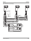
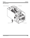
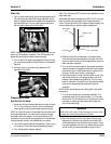
4. Connect the refrigeration unit side with the quick
connects (discharge and liquid). Make sure to
provide a discharge trap at back of refrigeration unit,
or bend discharge line down 12" and then up
smoothly (no kinks) to provide a trap.
5. If a low refrigerant charge is detected, recover and
recharge the system adding the unit name plate
charge.
6. Repair any damages to the line sets before
proceeding.
TESTING CO
2
CIRCUIT FOR LEAKS
It is advisable to test the system for leaks before turning
ON the water supply to the carbonator and connecting
the syrup tanks. If a leak does exist, it will be easier and
faster to make any correction.
1. Turn ON the CO
2
supply and adjust the primary
regulator to 90 psi (6.2 bar).
2. Position the CO
2
tank changeover valve handle (if
applicable) toward this regulator.
3. Move the air/CO
2
changeover valve to the CO
2
position (if applicable).
4. Allow the CO
2
gas to enter the system.
5. Wait for 2 or 3 minutes before turning OFF the CO
2
tank valve. This will allow the lines to expand under
pressure.
6. Turn OFF the CO
2
tank valve. Observe the pressure
on the high pressure gauge (not the 90 psi [6.2 bar]
operating gauge). The needle may drop
approximately 1 psi (.09 bar), but must remain
constant and not lose pressure. Wait for several
minutes.
If pressure continues to fall, this indicates there is a leak
in the system which must be corrected.
The greater the leak, the faster the pressure will drop.
The smaller the leak, the slower the gauge will drop.
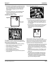
It may be necessary to use a soap solution at all
connections to locate a very small leak.
CO
2
gas must be present on all valves of the tower(s)
NOTE: All soap solution must be rinsed thoroughly from
tubing upon completion of testing.
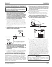
TESTING SYRUP CIRCUIT (5 GALLON TANKS ONLY)
Before connecting the syrup tanks to the system, the
syrup circuits must be tested for leaks with CO
2
gas.
1. Connect an empty syrup tank to pre-mix syrup
circuits.
2. Connect one of the CO
2
gas quick disconnects to
this tank. Allow the tank to fill with CO
2
gas.
3. Observe the pressure of the primary CO
2
tank
regulator (not the 90 psi [6.2 bar]).
4. Allow the CO
2
tank pressure to remain ON for a few
seconds. This will allow the lines to expand to
operating conditions.
5. Turn OFF the CO
2
tank cylinder.
6. Check all connections from the syrup tank through
the connections in the water bath area to all fittings
at rear of tower.
7. Check syrup circuitry on the tower by activating the
valve.
8. Follow the same procedure for the diet pre-mix
beverage circuit.
If no leaks are found in the syrup circuits and the
carbonated water circuit, the system is ready to be
insulated and placed in operation.