


32
MR-G50J-NZ
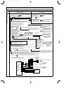
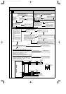
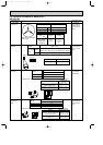
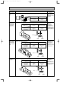
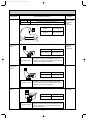
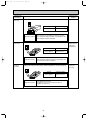
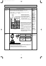
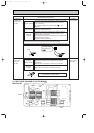
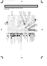
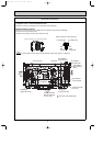
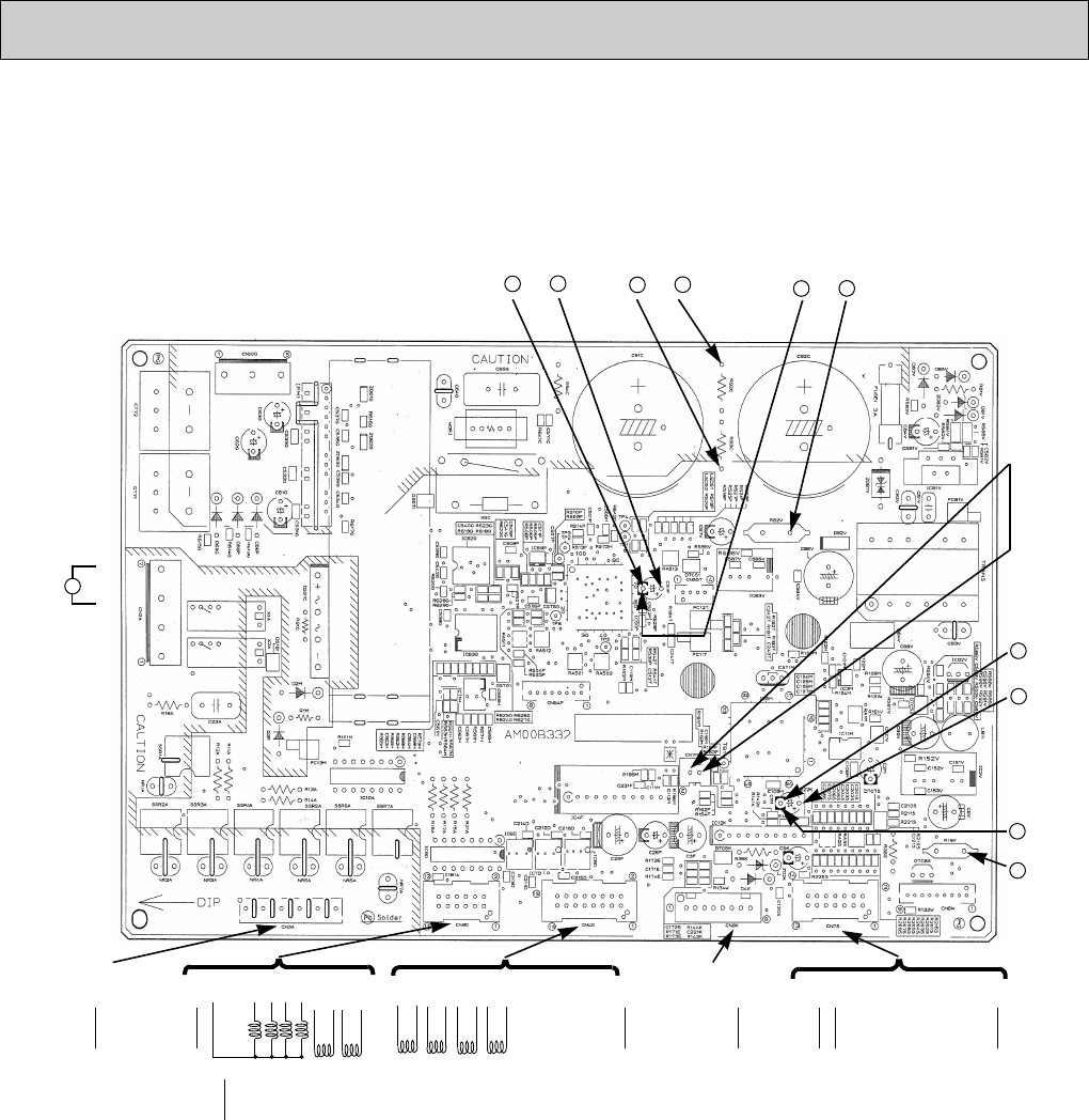
6-8 TEST POINT DIAGRAM OF CONTROL BOARD
}
Compressor
5 W phase
3 V phase
1 U phase
}
Compulsory
defrosting by
short circuit
CN4D
3 Defrost
heater
1 Refrigerator
compartment
DC +5V
(Inverter circuit)
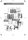
CN9DCN3A
CN7S
CN2A
~
1
2 GND
3 GND
4 Machine chamber fan motor (+)
5 Refrigerator fan motor FG signal
6 Machine chamber fan motor / Refrigerator fan motor driver IC powe source
7 Machine chamber fan motor FG signal
8 Fan motor +
9
10
11
12
13
14
15
16
}
1
2
3
4
5
6
7
8
9 LED for bacteria removal from water tank
10
11 Power suplly of three-way valve
12
1 Reception of operation panel data
2 Power supply to operation panel data
3
4 GND
5 Ice maker position switch
6 Water pump -
7 Ice maker (reverse)
8 Ice maker (rotation)
Electromagnetic three-way valve
}
Damper for refrigerator
compartment / slide compartment
}
}
Damper for ice making
compartment / versa compartment
1
2 Vegetable compartment LED
3 Door switch input
4 Freezer compartment thermistor
5 Ice making compartment thermistor
6 Vegetable compartment thermistor
7 Versa compartment thermistor
8 Slide chilled compartment thermistor
9 Defrost thermistor
10 Ice making tray thermistor
11 Refrigerator compartment thermistor
12
13
14 5V com
CN8K
}
Damper for freezer
compartment
}
+
–
DNG
DC280 ~ 330V
}
+
–
DC+12 ~ 20V
(Inverter circuit)
}
+
–
}
AC
230V
7
5
DC+5V
(Refrige-
rator
control
circuit)
}
+
–
DC+12
~ 13V
(Refrige-
rator
control
circuit)
}
+
–
}
1 Ice tray heater
3 Water pipe heater
5 Divider heater (I/S)
7 Vegetable compartment heater 1, 2
9
11 Rotational heater board
OA090-2.qxp 06.7.20 9:56 AM Page 32