


35
OPERATING PROCEDURE
PHOTOS
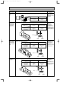
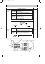
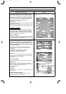
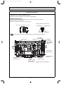
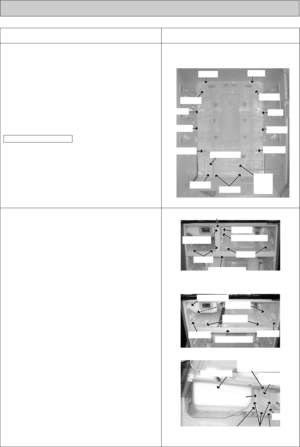
(4)Remove rivet E, and pull out the mirror hinge on the lower left
of the control panel to remove the connector. (See photo 5)
(5)Remove rivet F (two rivets) in the upper left and right side,
screw A (two screws) in the lower left and right side, and rivet
F (two rivets) in the lower. left and right side.
Detach catches (seven places).
(See photo 5)
(6)Detach catches (six places) on control panel (upper/ lower) and
then duct R (upper/ lower).
Control panel can be divided into the upper and lower part by
detaching catches (three places) on control panel (upper/ lower)
(The assembly consists of the following: Control panel [upper/
lower], motor damper for refrigerator compartment / slide chilled
compartment, refrigerator compartment thermistor, slide chilled
compartment thermistor, room light socket, refrigerator compart-
ment room light, and duct R [upper/ lower]).
Caution on assembly
To prevent poor contact of connectors, connect them properly.
Fix the control panel by inserting the lower catches (two places)
into the floor of refrigerator compartment.
3. Parts inside the ice making compartment, versa compart-
ment, vegetable compartment, and freezer compartment ➔
Partition I/ S ➔ Partition I/ S/ V ➔ Cover (IM) ➔ Automatic
Ice maker assembly ➔ Cover (lower) ➔ Partition V/ F ➔
Connector cover (right/ left) ➔ Fan grille ➔ Defrost heater,
Drip tray, DEF thermistor
(1)Remove interior parts out of ice making compartment,
versa compartment, vegetable compartment, and freezer
compartment.
(2)To detach them, pull out the doors of ice making
compartment, versa compartment, vegetable
compartment, and freezer compartment.
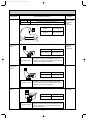
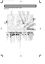
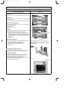
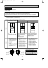
(3)Remove rivet E (one rivet), partition cover, and a connector.
Remove screw C (two screws) at the front side of refrigerator
and four rollers to pull out the partition.
(See photo 6)
Push up the lead wires so that they will not rub partition I/ S.
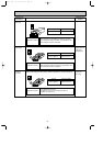
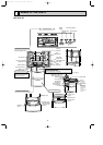
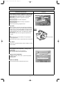
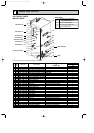
(4)Remove screw A (two screws) at the front of refrigerator.
Remove screw A (one screw each) and screw D (one screw
each) at the right and left side of inner wall.
Then lift up the partition.
(See photo 7)
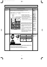
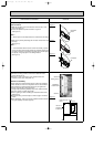
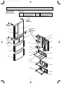
(5)Remove 2 rivets E and 3 catches in order to detach the cover.
(See photo 8)
(6)Pressing a catch upward, and pull Automatic Ice maker
assembly to the right side. (See photo 8)
Automatic ice maker assembly
Cover (IM)
Partition I/ S/ V
Caution on assembly
Partition I/ S
Control panel assembly
Duct R (upper/ lower)Control panel (upper/ lower)
Photo 5
Photo 6
Partition I/ S
Screws C
Partition cover
Rollers
Partition I/ S/ V
Rivet E
Photo 7
Tank holder
Screw D
Partition I/ S/ V
Screw D
Photo 8
Catches
Rivet E
Mirror hinge
Catch
Catch
Rivet F
Catch
Control
panel
(lower)
Screw A
Screw A
Rivet F
Screws A
Catch
w
Screws A
Catch (Automatic Ice
maker assembly)
Rollers
Tank holder
Cover
Rivet E
Cover (IM)
Rivet E
Rivet F
Rivet F
Automatic Ice
maker assembly
Catches
(Cover)
OA090-2.qxp 06.7.20 9:57 AM Page 35