11
W415-0223 / E / 03.05.09
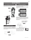
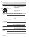
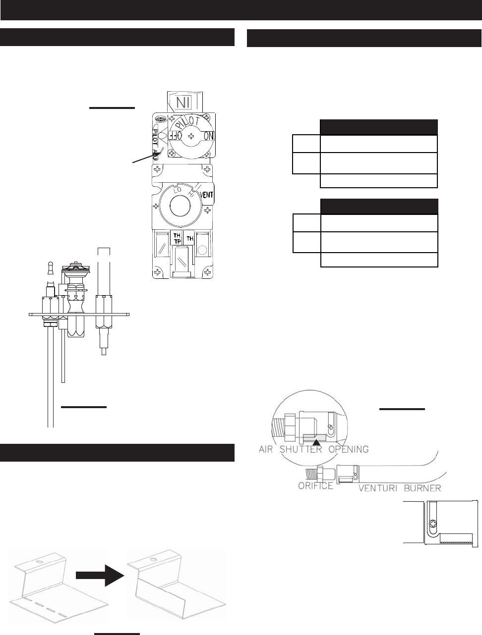
A mirror will let you see the opening
of the air shutter without removing the
burner. Scribe a line along the venturi
tube and air shutter cap. Open or close
according to the original opening by us-
ing the scribed line as your datum.
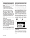
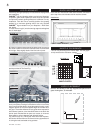
Remove the pilot screw cap. Adjust the pilot screw to provide
properly sized fl ame. Turn in a clockwise direction to reduce
the gas fl ow. Replace the pilot screw cap.
FIGURE 27
Air shutter adjustment
must only be done by a
qualifi ed gas installer!
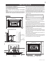
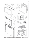
FIGURE 30
This unit is approved for use with a 2" liner for air intake and
a 3" liner for exhaust. For best performance, however, it is
recommended to use two 3" liners.
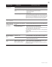
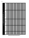
Air shutter settings will differ depending on the liner system
used. Use the charts below to determine the correct air shut-
ter setting:
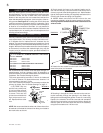
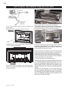
Some vent confi gurations may display a very active fl ame.
If this appearance is not desirable, the vent exit may be re-
stricted using the restrictor plate shown in FIGURE 6b. Bend
the fl ap up as shown to reduce the velocity of the exhaust
gases, slowing down the fl ame pattern and creating a more
traditional appearance.
FIGURE 29
Closing the air shutter will cause a more yellow fl ame, but can
lead to carboning. Opening the air shutter will cause a more
blue fl ame, but can cause fl ame lifting from the burner ports.
The fl ame may not appear yellow immediately; allow 15 to 30
minutes for the fi nal fl ame colour to be established.
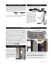
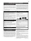
HELPFUL HINT:
FLAME MUST
ENVELOPE
UPPER 3/8" TO 1/2" OF
THERMOCOUPLE &
THERMOPILE
PILOT
BURNER
THERMOCOUPLE
THERMOPILE
FIGURE 28
ADJUSTMENTS
PILOT BURNER ADJUSTMENT
VENTURI ADJUSTMENT
VENT RESTRICTION
3"/ 3" LINER SYSTEM
NG 1/16"
LP 3/16"
AIR SHUTTER SETTING
2"/ 3" LINER SYSTEM
NG 1/8"
LP 5/16"
AIR SHUTTER SETTING
PILOT
SCREW