7
W415-0223 / E / 03.05.09
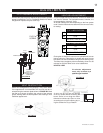
For ease of accessibility, an optional remote wall switch
or millivolt thermostat may be installed in a convenient
location. Route 2-strand solid core millivolt wire from
the gas fi replace insert to the wall switch / millivolt
thermostat. The recommended maximum lead length
depends on the wire size:
WIRE SIZE MAX. LENGTH
14gauge 100 feet
16gauge 60 feet
18gauge 40 feet
Do not connect either the wall switch, thermostat
or gas valve to electricity (110 VOLTS).
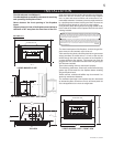
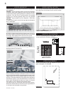
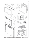
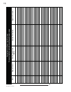
To adjust the trim: If the mitre is out of alignment, open each
side and loosen the two screws at either side trim hinge. Slide
the trim up or down to adjust and re-tighten screws. There is
also a very slight in/out adjustment that can be made.
Note: Since the side panels open and close, to access the
controls, a gap is necessary at the mitre joint.
The top trim piece has an adjustable securing bracket which
enables the trim to be secured to the fi rebox shell.
In order to close off the fi replace opening or if the opening is
larger than the 3- or 4-sided aluminium extrusion trim kits, it is
recommended to reduce the opening using a noncombustible
material such as ceramic tile, marble, etc or the GIZBP6-3 or
GIZBP6-4 backer plate kits. The outside edge of the backer
plate is fi nished off with gold trim included in each kit. A
deluxe fl ashing kit complete with marquis trim may also be
used to complete the installation. These fl ashing and trim
combinations are available in 6 and 9 inch widths as well as
many fi nishes to accent any room decor. Mounting brackets,
GIZBRKT, are required to install the deluxe fl ashing. Detailed
installation instructions are included with each kit.
If this unit is being installed into an existing wood burning,
zero clearance fi replace, then be aware of this precaution:
Any circulation air opening may be covered (with non-
combustible material) but not sealed!
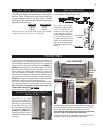
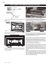
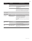
The insert can be equipped
with either a 3- or 4-sided
trim kit to fi nish off the fi re-
place opening. Slide the trim
assembly over the keyholes
(2 per side) and drop into
place. If installing the optional
3- or 4-sided backer plate
(GIZBP6-3 or GIZBP6-4), it
must be hung prior to the trim
kit installation using the same
keyholes.
FIGURE 8
FIRE VIEWING DOOR
FIGURE 11
FIGURE 6
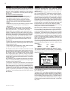
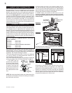
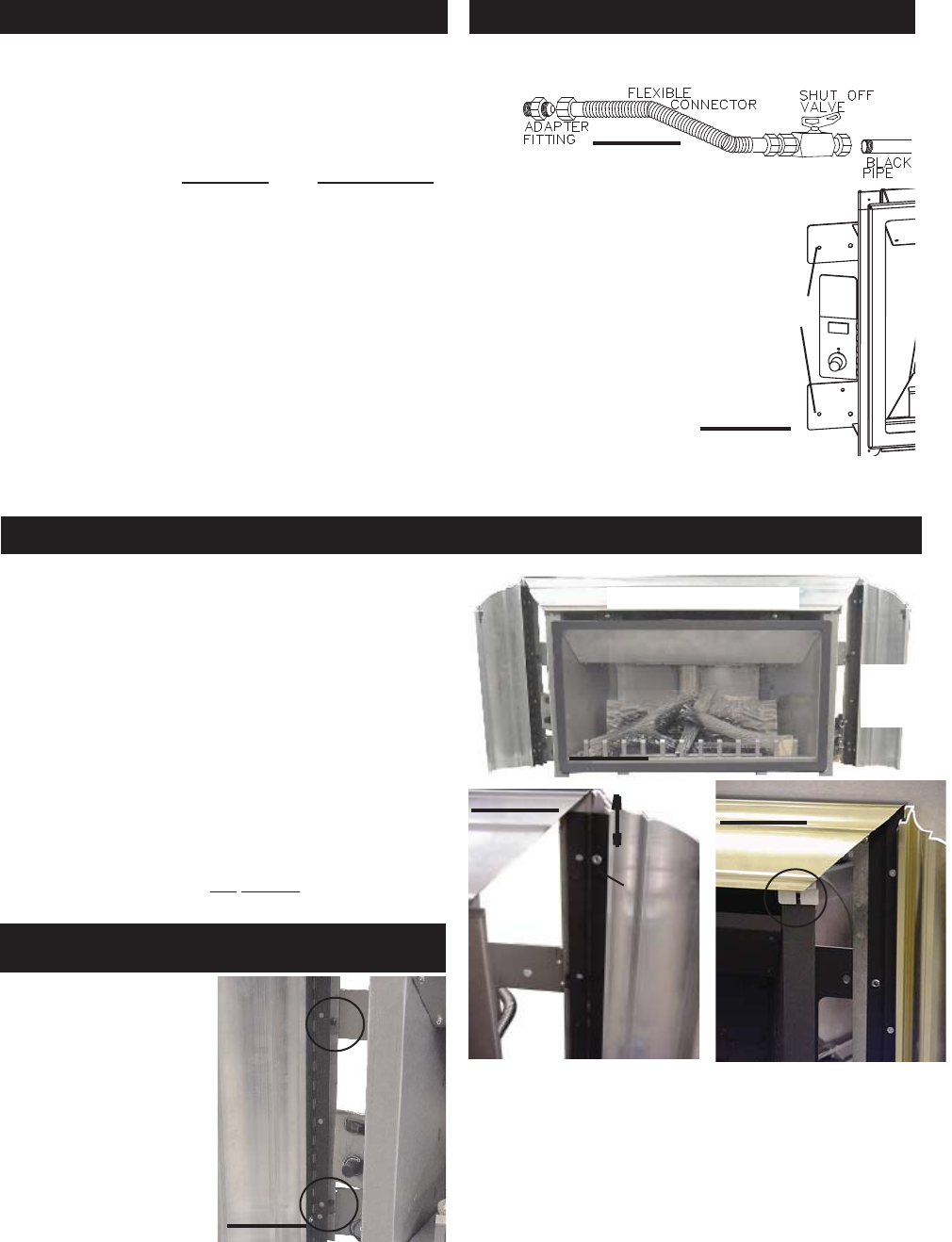
The insert may now be
pushed into its fi nal position
inside the wood-burning
fi replace. Secure the insert
to the fi replace using per-
forated strapping attached
to the two securing holes
on either side of the unit as
shown. We recommend that
the trim be installed before
the unit is placed into its fi nal
position.
SECURING
HOLES
FIGURE 7
FIGURE 9
VALVE
CONTROL
DOOR
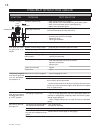
Install suitable supply piping connection to the
3
/
8
" fl ex con-
nector supplied (as per local gas codes).
FIGURE 10
LOOSEN
SCREWS
SLIDE TO
ADJUST
WALL SWITCH / THERMOSTAT GAS INSTALLATION
FINISHING
ALUMINIUM EXTRUSION TRIM KIT
INSTALLATION