6
W415-0223 / E / 03.05.09
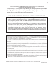
2" OVERLAP
EXHAUST
SEALANT
HI-TEMP
INTAKE
VENT
CONNECTION
ASSEMBLY
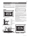
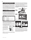
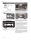
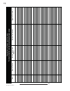
Move the insert close to its fi nal position inside the wood-
burning fi replace. This unit is equipped with 6 levelling screws
located as follows: two are on either side of the circulation
blower on the rear panel; four are located front and back on
either side beneath the log support. Level using four of the lev-
elling screws. See Figure 1a. Levelling the unit will eliminate
rocking or excessive noise when the fan is in operation. Once
the unit is level, move it partially into place within the fi replace
to allow for all connections to be made. It is not practical to
level the insert once the it has been installed. Determine the
required depth prior to installing the unit and adjust the four
levelling screws accordingly.
Chimney installation must conform to both national and local
code requirements. The chimney must be lined with one 2"
or 3" diameter liner for intake and one 3" diameter liner for
exhaust. The minimum and maximum vent lengths are 10 and
35 feet respectively. Recommended Napoleon kits come in 3
lengths: While the liners must be continuous from the fi replace
to the terminal, to achieve the needed length, they may be
coupled, using an aluminium coupler, provided installation is
sealed & secured.
We recommend that exhaust vents that pass through un-
heated spaces, such as a garage or attic, be wrapped in a
protective sleeve to minimize condensation and reverse fl ow
symptoms. See Trouble Shooting for details.
This unit is approved for use with a 2" liner for air intake and
a 3" liner for exhaust. For best performance, however, it is
recommended to use two 3" liners.
If a 2" liner is used for the intake, it is necessary to adjust the
primary air shutter. See "Air Shutter Settings" on page 11.
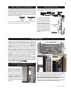
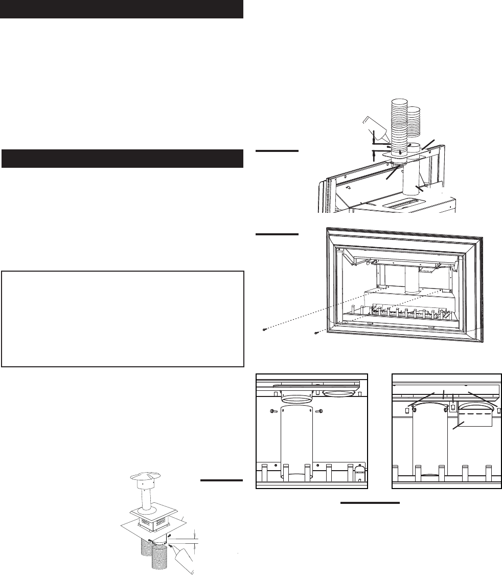
1. OUTSIDE: Slip one
end of a liner a minimum of
2" over one of the collars of
the terminal. Secure using
3 screws. Then seal the
joint and screw heads with
high temperature seal-
ant. Repeat with the other
liner.
NOTE: We recommend that the other end of the exhaust liner
be marked to eliminate the exhaust liner being connected to
the intake collar at the unit.
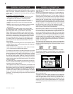
FIGURE 3
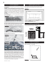
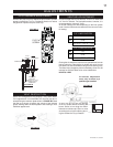
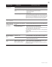
4. Detach the two screws from the back of the fi rebox and
remove the panel, as illustrated.
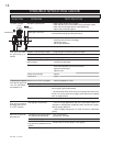
5. Reaching in through the insert, manoeuvre the vent con-
nection assembly through the openings in the fi rebox top,
taking care not to damage the gasket. In case of a low ceiling
fi replace, the extension should be removed and reinstalled
after the vent connection is secured to the fi rebox. Attach the
restrictor plate to the centre stud and secure the assembly
using the three studs and ¼-20 hex nuts.
INSERT VENT CONNECTION
CHIMNEY CONNECTION
FIGURE 4
FIGURE5a-b
1-2" & 1-3" DOUBLE PLY ALUMINUM LINER-INLET AND EXHAUST
&
2-3" TO 2" REDUCER:
GDI-2320KT VENT KIT 20FT
GDI-2325KT VENT KIT 25FT
GDI-2335KT VENT KIT 35FT
2-3" DOUBLE PLY ALUMINUM LINER-INLET AND EXHAUST:
GDI-320KT VENT KIT 20FT
GDI-325KT VENT KIT 25 FT
GDI-335KT VENT KIT 35 FT
2. Gently stretch the liners to the required lengths and in-
sert into the chimney. Place the terminal onto the top of the
chimney cap and fi t the fl ashing plate to suit. Make weather
tight by sealing with caulking (not supplied) and fasten to the
chimney with screws and plugs (not supplied)
3. INSIDE: Attach and secure the fl ex liners to the vent
connection assembly using the same procedure as before,
ensuring that the marked exhaust liner is attached to the
exhaust collar.
EXHAUST
COLLAR LABELED
INTAKE
OVERLAP
SEALANT
HI-TEMP
FLASHING
PLATE
2"
TERMINAL
GDI-223
FIGURE 2
RESTRICTO
PLATE
STUDS
VENT
CONNECTOR
EXTENSION