


Introduction Chapter 1
GPIB-ENET for Macintosh 1-4 © National Instruments Corp.
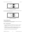
The Top Panel LEDs
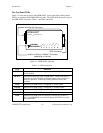
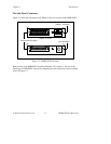
Figure 1-1 shows the top panel of the GPIB-ENET. Seven status light-emitting diodes
(LEDs) are mounted on the GPIB-ENET top panel. The LEDs show the current status of
the GPIB-ENET at all times. Table 1-1 describes each LED.
Ethernet AUI Connector
GPIB Connector
Location of Coax or 10Base-T Connector
(depending on version)
GPIB-ENET
ETHERNET IEEE 488 Controller
POWER
READY
TALK
LISTEN
TRANSMIT
RECEIVE
LINK
NATIONAL
INSTRUMENTS
®
Figure 1-1. GPIB-ENET Top Panel
Table 1-1. LED Descriptions
LED Indication
POWER Indicates that power has been supplied to unit and ON/OFF switch is
in ON position.
READY Indicates the functional state of GPIB-ENET. When GPIB-ENET is
powered on, this LED flashes and then becomes steady when box is
ready for operation. Continuous flashing indicates an error has
occurred.
TALK Indicates that GPIB-ENET is configured as a GPIB Talker.
LISTEN Indicates that GPIB-ENET is configured as a GPIB Listener.
TRANSMIT Indicates that GPIB-ENET is transmitting onto the Ethernet network.
RECEIVE Indicates that GPIB-ENET is receiving Ethernet network traffic.
LINK Indicates that GPIB-ENET has detected a twisted pair (10Base-T)
link. For GPIB-ENET coax and AUI options, this LED is not used
and remains OFF.