


Chapter 4 Installation Verification and Troubleshooting
© National Instruments Corp. 4-3 GPIB-ENET for Macintosh
READY LED Signaling
The READY LED has several purposes on the GPIB-ENET. When you first power on
the GPIB-ENET, the READY LED flashes while it completes its power-on self tests.
When all the tests complete successfully and the IP address is assigned, from either
nonvolatile memory or the network, the READY LED remains steady, indicating that the
unit is ready to operate.
During operation, there are times when the READY LED might flash again. The first
time occurs after upgrading the EEPROMs, when the GPIB-ENET reports status on the
operation. Refer to Appendix B, Utilities, for more information. At other times, the
GPIB-ENET alerts you of internal errors. For assistance in correcting this problem,
please record the pattern that the READY LED flashes, and contact National
Instruments.
Note: By recording the READY LED status messages before calling National
Instruments, you can save yourself time, and the GPIB Product Support
Department can answer your questions more accurately and efficiently.
Do not switch off power to your GPIB-ENET before recording the flashing
READY LED pattern.
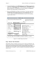
READY LED signaling can report up to 100 different errors. The errors are numbered
from 0 to 99 and are reported through sequences of READY LED flashes.
Step 1. Count the Long Flashes
A three-second interval, during which the READY LED is OFF, separates each repetition
of the sequence. The sequence begins with a series of long one-second flashes; that is,
one second ON, one second OFF. These long flashes represent the digit in the tens
column. There can be one to ten long flashes, which represent digits 0 through 9. For
example, one long flash represents a 0 in the tens column, two long flashes represent the
digit 1 in the tens column, and ten long flashes represent a 9 in the tens column.
Step 2. Count the Short Flashes
The long flashes are followed by shorter flashes; each lasting about one-fifth of a second.
These short flashes represent the digit in the ones column. Again, there can be one to ten
flashes which represent the digits 0 through 9. For example, one short flash represents
the digit 0 in the ones column, two short flashes represent the digit 1 in the ones column,
and ten short flashes represent a 9 in the ones column.
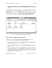
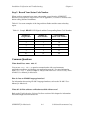
Using this method, the READY LED flashes the following sequence to represent status
message 11.
<three seconds OFF> <two long flashes> <two short flashes> <three seconds OFF>…
The READY LED flashes the following sequence to represent status message 30.
<three seconds OFF> <four long flashes> <one short flash> <three seconds OFF>…