


C1547M (7/03) 11
U5
U11
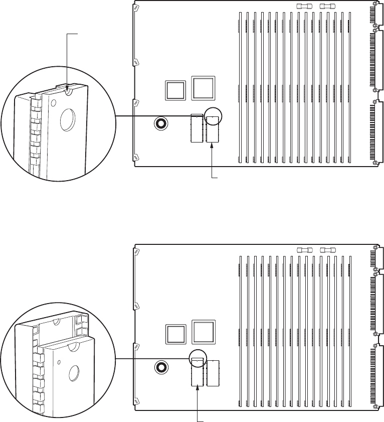
U12 PROM CHIP
U12
U10
ALIGNMENT
NOTCH
U5
U11
U10 RAM CHIP
U10
U12
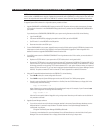
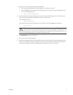
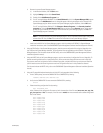
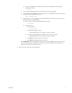
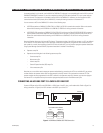
Figure 3. U12 PROM Chip
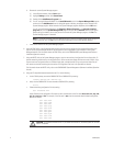
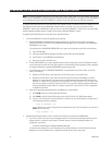
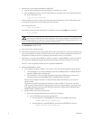
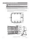
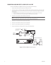
Figure 4. U10 RAM Chip
3. Replace the existing U12 PROM chip on the video output card with the chip supplied in the upgrade kit:
a. Locate the existing U12 PROM chip on the video output card (refer to Figure 3).
b. Using the provided extraction tool, remove the U12 PROM chip from its socket. Remove the chip slowly to avoid
damaging the socket.
c. Remove the replacement PROM chip from the electrostatic bag.
d. Note the alignment notch at the top of the chip (refer to Figure 3). Orient the chip so that the notch on the chip
aligns with the notch that is drawn on the surface of the circuit board. Verify pin-to-socket alignment, and then
carefully press the chip into its socket until the chip is seated completely.
4. Erase the RAM (random access memory) stored on the U10 chip:
a. Locate the existing U10 RAM chip on the video output card (refer to Figure 4). Note the location of the chip in its
socket (the top two pins on either side of the socket are not used).
b. Using the provided extraction tool, remove the U10 chip from its socket. Remove the chip slowly to avoid damaging
the socket.
c. Wait two minutes and then reinstall the chip into its socket in the same position noted in step 4a. Verify pin-to-
socket alignment, and then carefully press the chip into its socket until the chip is seated completely.