


C1547M (7/03) 13
APPENDIX B. CONNECTING AN ASCII COMMUNICATIONS DEVICE TO THE CM9740-CC1
As stated previously in this manual, version 8.03.012 of CM9740-CC1 software is not compatible with version 3.20 or earlier of
CM9760-DT/CM9760-DT4 software. If you wish to replace the existing DT/DT4 device (external DT) in your system with the
use of the internal DT software that is provided in version 8.03.012 of CM9740-CC1 software, you must connect the ASCII
communications device (ACD) directly to the CM9740-CC1, thereby eliminating connection to the external DT.
You can connect an ACD to the CM9740-CC1 in either of the following ways:
• ACD DB9 connection to CM9740-CC1 DB9 (COM 1 or COM 2) via RS-232 communication standard. Refer to the section
below titled
Connecting an ACD DB9 Port to a CM9740-CC1 DB9 Port
for wiring connection information.
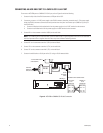
• ACD DB9 (RS-232) connection to CM9740-CC1 RJ-45 (RS-422). In this case, the Pelco PV130 RS-232/RS-422 converter is
used to provide a bidirectional electrical interface between the RS-232 port of the ACD and the RS-422 port of the CC1.
Refer to the section below titled
Connecting an ACD DB9 Port to a CM9740-CC1 RJ-45 Port
for wiring connection
information.
Note the following about use of the internal DT software. The operator number of the ACD that connects to a CC1 port defined
as an internal DT in the Comms setup file (IDT equipment number 48) is automatically assigned the same number as the CC1
port number. As a result, when replacing an external DT with the internal DT, you may need to reprogram operator-related data
using System Manager (version 8.03.012). Operator-related data is included in the following:
• Operators setup file
• Operator access dialog box in the following system setup files:
– Cameras setup file
– Macros setup file
– Alarms setup file
– General Purpose Interface (GPI) setup file
– Link cameras setup file
Note that you can avoid the need to reprogram operator-related data by connecting the ACD to an available CC1 port whose
number matches the operator number that was programmed for the ACD when it was connected to an external DT. (The
operator number that was programmed for the ACD is defined in the Operators setup file.) However, you must then program
the internal DT as a keyboard and may then need to reprogram keyboard access in the Monitors setup file.
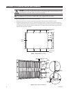
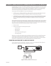
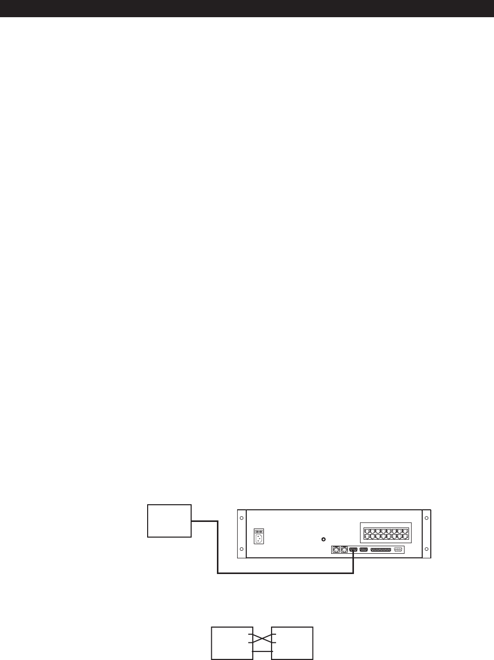
CONNECTING AN ACD DB9 PORT TO A CM9740-CC1 DB9 PORT
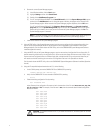
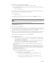
Connect a DB9 port of the ACD to the DB9 COM 1 or COM 2 port of the CC1 using a null modem cable. Refer to Figure 5 for
wiring connections. In Figure 5, the ACD connects to the COM 1 port of the CC1.
56789101112
1314 1516 1718 19 20
CM9740-CC1
ACD MALE
DB9 SERIAL
PORT
RS-232 NULL MODEM CABLE
PIN 2 = RX
PIN 3 = TX
PIN 5 = GND
NULL MODEM CABLE WIRING
ACD
DB9 PORT
CM9740-CC1
DB9 PORT
PIN 2 = RX
PIN 3 = TX
PIN 5 = GND
Figure 5. ACD DB9 to CM9740-CC1 DB9 Connection