


14 C1547M (7/03)
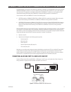
CONNECTING AN ACD DB9 PORT TO A CM9740-CC1 RJ-45 PORT
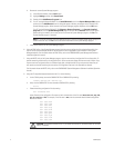
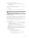
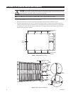
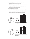
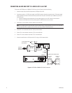
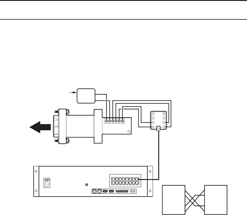
To connect an ACD DB9 port to a CM9740-CC1 RJ-45 port, refer to Figure 6 and do the following:
1. Connect the 9-pin side of the PV130 converter to a DB9 port of the ACD.
2. If necessary, connect a +12 VDC power supply to the PV130 converter; otherwise, proceed to step 3. (The power supply
allows the PV130 converter to communicate serial port data over wire pairs for distances up to 4,000 feet [1,219 m] on
the RS-422 side.)
a. Connect the black and white striped wire from the power supply to the +12 VDC terminal on the converter.
b. Connect the solid black wire from the power supply to the GND terminal on the converter.
3. Connect RX+ on the converter to terminal 8 (RX+) on the wall block.
NOTE: The numbering of the screw terminals on the wall block shown in Figure 6 applies to the Pelco RJ-45 wall block. A
wall block purchased from a supplier other than Pelco may have a different numbering scheme.
4. Connect RX- on the converter to terminal 7 (RX-) on the wall block.
5. Connect TX+ on the converter to terminal 1 (TX+) on the wall block.
6. Connect TX- on the converter to terminal 2 (TX-) on the wall block.
7. Connect the wall block to an RJ-45 port of the CC1 using an RJ-45 reversed cable.
56789101112
1314 1516 1718 19 20
CM9740-CC1
PIN 1 = TX+
PIN 2 = TX-
PIN 7 = RX-
PIN 8 = RX+
REVERSED CABLE CONNECTIONS
WALL BLOCK
RJ-45
CONNECTOR
CM9740-CC1
RJ-45
CONNECTOR
PIN 1 = TX+
PIN 2 = TX-
PIN 7 = RX-
PIN 8 = RX+
RS-422
REVERSED
CABLE
PV130
TX-
TX+
R
X
-
R
X
+
GND
+12
VD
C
1
2
3
4
8
7
6
5
+12 VDC
GND
+12 VDC POWER SUPPLY
(IF NECESSARY)
ACD MALE
DB9 SERIAL
PORT (RS-232)
WALL
BLOCK
Figure 6. ACD DB9 to CM9740-CC1 RJ-45 Connection