


1-8
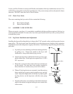
c. Connect the negative (-) test probe to pilot bracket.
d. Connect the positive (+) test probe to to one of the High Limit terminal connections
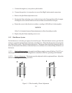
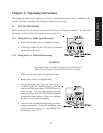
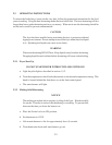
e. Remove the pilot flame adjustment cover.
f. Turning the flame adjusting screw clockwise lowers the flame and the millivolt output.
Turning the screw counterclockwise increases flame size and millivolt output.
g. Rotate the screw in the direction to achieve a reading of 400 ±50 mv for thermopiles.
NOTICE
Allow 3 to 5 minutes between flame adjustments to allow the reading to settle.
h. Replace the pilot flame adjusting screw cover.
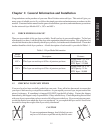
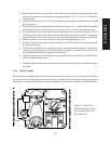
1.5.3 Main Burner System
For the burners to work, the gas supply valve must be open. The main burner receives gas from the
main gas supply through the thermostatically controlled valve. When the thermostat is turned up the
gas control valve opens. The pilot ignites the burners. The burner flame should be adjusted at the air
collar (at the bottom of the burner) so the the flame are a soft blue color without lifting off the face of
the burner.
1.5.3.1 Gas Line Requirements - A properly installed gas supply system will deliver 7.0 ±2.0" w.c.
natural gas (12.0 ±2.0" w.c. LP) to all appliances connected to the line, operating at full demand.
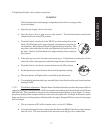
1.5.3.2 Burner Adjustment - The burners must be adjusted to deliver optimum flame. Adjust the
burner flame using the following procedure.
Figure 1-1 Pilot Assembly, Flame Adjustment
BA