27
INSTALLATION
Check the ap pli ance is electrically safe and gas sound when you have fi nished.
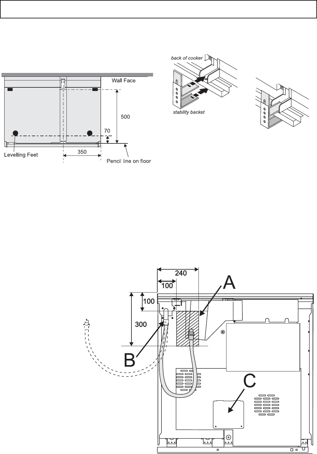
Fitting a stability bracket
A stability bracket or chain (not supplied by with the
cooker) should be fi tted when the cooker is connected to
a fl exible gas supply.
When fi tting a stability bracket read these instructions
together with the leafl et supplied with the bracket.
1. Place the cooker in its intended position and level
the cooker.
2. Draw a pencil line 70mm from the front edge of the
levelling feet.
3. Mark the centre line for the bracket by measuring
550mm from the left hand side of the cooker.
4. Lower the front roller and move the cooker forward.
5. Measure back from the pencil line 550mm to locate
the front edge of the bracket. Fix the bracket to the
fl oor.
6. Measure the height from fl oor level to engagement
edge in back of cooker. Add 3mm to this dimension
and assemble the stability bracket to this height. (i.e.
from fl oor level to underside of the top member) and
ensure the bracket does not foul the oven burner
assembly.
Gas Connection
Must be in accordance with the relevant standards. A
hose is not supplied by with the cooker. Hoses may be
purchased at most builders’ merchants.
The Gas sup ply needs to terminate with a down facing
bayonet. The rear cover boxes limit the position of the
supply point. The gap between the cooker rear cover
boxes and the rear wall when the cooker is pushed back is
only 50mm.
Because the height of the cooker can be adjusted and
each connection is diff erent it is diffi cult to give precise
dimensions. Ideally the house supply bayonet should be
in the shaded area (A) shown in the diagram. Alternative
connect from the side or use a Micropoint™ connection
hose and connector.
view from the rear
A appliance gas inlet
B position for gas supply connector,
alternatively from the side or use
a Micropoint™ connection hose
and connector.
C electrical terminal cover


