


11
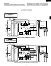
R-930AK
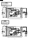
R-930AW
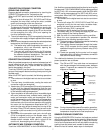
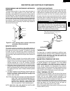
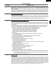
OUTER CASE SWITCHES
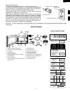
The two outer case switches are mounted near the power
supply cord at the oven cavity rear plate. When the outer
case cabinet is installed with the screws, one of the screws
pushes the actuator and then the actuator pushes each
plungers of the two outer case switches and their contacts
are closed. When a cabinet mounting screw which is push-
ing the actuator is removed, the two outer case switches
interrupt the circuit to the all components.
WARNING
The circuit to all components can be connected to the
power supply without the outer case cabinet by reinstall-
ing the cabinet mounting screw. BUT AT THAT TIME,
NEVER TOUCH ANY PARTS OF THE HIGH VOLTAGE
CIRCUIT TO AVOID ELECTROCUTION.
OUTER CASE
CABINET
OUTER CASE
SWITCHES
ACTUATOR
This outer case mounting screw is
pushing the actuator.
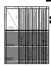
THERMISTOR
The thermistor is a negative temperature coefficient type.
The temperature in the oven cavity is detected through the
resistance of the thermistor, and then the control unit
causes the heater relay to operate, thus the current to the
heating element is turned ON/OFF.
MAGNETRON TEMPERATURE FUSE.
The temperature fuse located on the waveguide is designed
to prevent damage to the magnetron if an over heated
condition develops in the megnetron due to cooling fan
failure, obstructed air guide, dirty or blocked air intake, etc.
Under normal operation, the temperature fuse remains
closed. However, when abnormally high temperatures are
reached within the magnetron, the temperature fuse will
open at 302˚F(150˚C) causing the oven to shut down.
CONV. THERMAL CUT-OUT
The thermal cut-out located on the left side of the thermal
protection plate (left) is designed to prevent damage to the
heater unit if an over heated condition develops in the
heating unit due to convection fan failure, thermistor failure,
obstructed air ducts, dirty or blocked air intake, etc.
Under normal operation, the thermal cut-out remains closed.
However, when abnormally high temperatures are reached
within the heater unit, the thermal cut-out will open at
302˚F(150˚C) causing the oven to shut down.
When the thermal cut-out has cooled, the thermal cut-out
closes at 266˚F(130˚C).
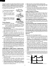
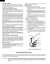
DOOR SENSING AND SECONDARY INTERLOCK
SWITCHES
The door sensing switch in the primary interlock system is
mounted in the upper position on the latch hook, the
secondary interlock switch is mounted in the lower position
on the latch hook. They are activated by the latch heads on
the door. When the door is opened, the switches interrupt
the circuit to all components. A cook cycle cannot take place
until the door is firmly closed thereby activating both inter-
lock switches. The primary interlock system consists of the
door sensing switch and primary interlock relay located on
the control circuit board.
DESCRIPTION AND FUNCTION OF COMPONENTS
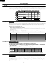
Figure D-1. Door sensing switch, monitor switch and
secondary interlock switches
MONITOR SWITCH
The monitor switch is mounted on the middle position of
latch hook. It is activated (the contacts opened) by the lower
latch head while the door is closed. The switch is intended
to render the oven inoperative by means of blowing the
monitor fuse when the contacts of the primary interlock relay
and secondary interlock switch fail to open when the door is
opened.
Functions:
1. When the door is opened, the monitor switch contact
close (to the ON condition) due to their being normally
closed. At this time the door sensing and secondary
interlock switches are in the OFF condition (contacts
open) due to their being normally open contact switches.
2. As the door goes to a closed position, the monitor switch
contacts are first opened and then the door sensing
switch and the secondary interlock switch contacts close.
(On opening the door, each of these switches operate
inversely.)
3. If the door is opened, and the primary interlock relay and
secondary interlock switch contacts fail to open, the
monitor fuse blows simultaneously with closing of the
monitor switch contacts.
CAUTION: BEFORE REPLACING A BLOWN MONITOR
FUSE TEST THE DOOR SENSING SWITCH,
PRIMARY INTERLOCK RELAY, SECONDARY
INTERLOCK SWITCH AND MONITOR
SWITCH FOR PROPER OPERATION. (RE-
FER TO CHAPTER “TEST PROCEDURE”).
NOTE: MONITOR FUSE AND MONITOR SWITCH ARE
REPLACED AS AN ASSEMBLY.
DOOR SENSING
SWITCH
MONITOR FUSE
MONITOR SWITCH
SECONDARY
INTERLOCK
SWITCH