


23
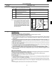
R-930AK
R-930AW
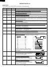
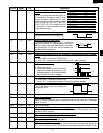
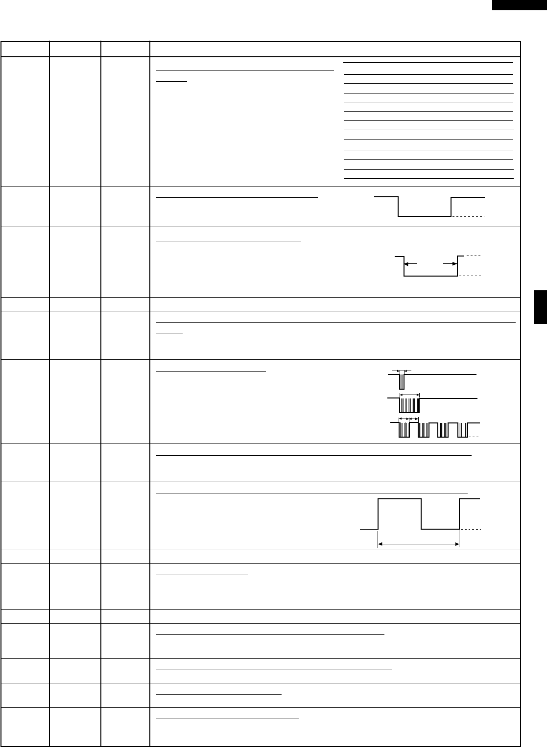
17 P51 OUT Magnetron high-voltage circuit driving
signal.
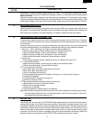
To turn on and off the cook relay(RY2). In
P-HI operation, the signals holds "L" level
during microwave cooking and "H" level
while not cooking. In other cooking modes
(P-90, P-80, P-70, P-60, P-60, P-50, P-40,
P-30, P-20, P-10, P-0) the signal turns to
"H" level and "L" level in repetition accord-
ing to the power level.
18 P50 OUT Damper motor relay driving signal.
To turn on and off shut-off relay(RY4).
19 P47 OUT Heating element driving signal.
To turn on and off shut-off relay(RY3). "L" level during
convection cooking; "H" level otherwise. During con-
vection cooking, the signal becomes "H" level when
the temperature of the oven cavity exceeds the
predetermined temperature.
20-21 P46-P45 OUT Terminal not used.
22 P44 OUT Timing signal output terminal for temperature measurement(OVEN THERMIS-
TOR).
"H" level (GND) : Thermistor OPEN timing.
"L" level (-5V) : Temperature measuring timing.(Convection cooking)
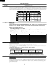
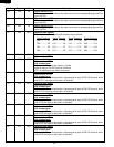
23 P43 OUT Signal to sound buzzer.
A: key touch sound.
B: Completion sound.
C: When the temperature of the oven cavity
reaches the preset temperature in the
preheating mode, or when the preheating
hold time (30 minutes) is elapsed.
24 P42 OUT Timing signal output terminal for temperature measurement(OVEN).
"H" level (GND) : Ttermistor OPEN timing.
"L" level (-5V) : Temperature measuring timing.(Convection cooking)
25 INT1 IN Signal to synchronize LSI with commercial power source freqency.
This is the basic timing for all real time
processing of LSI.
26 P40 IN Connected to GND.
27 RST IN Auto clear terminal.
Signal is input to reset the LSI to the initial state when power is applied. Temporarily
set to "L" level the moment power is applied, at this time the LSI is reset. Thereafter
set at "H" level.
28/29 XCIN/XCOUT OUT Terminal not used.
30 XIN IN Internal clock oscillation frequency setting input.
The internal clock frequency is set by inserting the ceramic filter oscillation circuit with
respect to XOUT terminal.
31 XOUT OUT Internal clock oscillation frequency control output.
Output to control oscillation input of XIN.
32 VSS IN Power source voltage: -5V.
VC voltage of power source circuit input.
33 P27 IN Signal coming from touch key.
When any one of G-1 line keys on key matrix is touched, a corresponding signal from
P17 - P17 will be input into P27. When no key is touched, the signal is held at "L" level.
Pin No. Signal I/O Description
VARI MODE ON TIME OFF TIME
P-HI (100% power) 32 sec. 0 sec.
P-90 (approx. 90% power) 30 sec. 2 sec.
P-80 (approx. 80% power) 26 sec. 6 sec.
P-70 (approx. 70% power) 24 sec. 8 sec.
P-60 (approx. 60% power) 22 sec. 10 sec.
P-50 (approx. 50% power) 18 sec. 14 sec.
P-40 (approx. 40% power) 16 sec. 16 sec.
P-30 (approx. 30% power) 12 sec. 20 sec.
P-20 (approx. 20% power) 8 sec. 24 sec.
P-10 (approx. 10% power) 6 sec. 26 sec.
P-0 (0% power) 0 sec. 32 sec.
ON
OFF
H : GND
L
ON
OFF
During
cooking
L
GND
H.
(Convection)
A
B
C
H: GND
L
0.1 sec
2.0 sec
1.0 sec
1.0 sec
16.7 msec.
H : GND
L (-5V)