


30
R-930AK
R-930AW
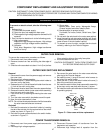
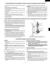
CONTROL PANEL ASSEMBLY AND CONTROL UNIT REMOVAL
To remove the control panel, procedure as follows:
1. Disconnect oven from power supply and remove outer
case.
2. Discharge high voltage capacitor.
3. Disconnect connector CN-A, CN-E and CN-F from the
control unit.
4. Disconnect the wire leads from the relays RY1, RY2 and
RY3.
5. Remove one (1) screw holding the control panel back
plate to the chassis support.
6. Remove two (2) screws holding the bottom edge of the
back plate to the cabinet base.
7. Remove one (1) screw holding the back plate to the oven
cavity flange.
8. Lift up and pull the control panel assembly forward.
Replacement of individual component is as follows;
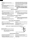
CONTROL UNIT AND KEY UNIT
1. Disconnect the wire connector from the control unit.
2. Remove the four (4) screws holding the panel frame to
the back plate.
3. Separate the panel frame and back plate.
4. Remove the three (3) screws holding the control unit to
the panel frame.
5. Lift up the control unit and disconnect the key connector
from the control unit.
6. Now, the control unit and frame assembly are separated.
NOTE; 1. Before attaching a new key unit, remove remaining
adhesive on the control panel frame surfaces
completely with alcohol and so on.
2. When a attaching the key unit to the control
panel frame, adjust the lower edge and right
edge of the key unit to the correct position of the
control panel frame.
3. Stick the key unit firmly to the control panel
frame by rubbing with soft cloth not to scratch.
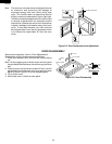
8. Remove the magnetron air guide from the waveguide.
9. Disconnect wire leads from the fan motor.
10. Release the main harness from the hole of the fan duct.
11. Release the thermistor harness from the hole of the fan
duct.
12. Release one (1) tab holding the fan duct to the rear
cabinet.
13. Release one (1) tab holding the fan duct to the air guide
(Right).
14.Remove the fan duct assembly from the oven.
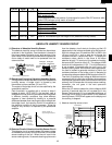
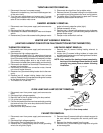
15.Remove the fan blade from the fan motor shaft according
the following procedure.
1) Hold the edge of the rotor of the fan motor by using a pair
of grove joint pliers.
CAUTION:
* Make sure that any pieces do not enter the gap
between the rotor and the stator of the fan motor
because the rotor is easily shaven by pliers and
metal pieces may be produced.
* Do not touch the pliers to the coil of the fan motor
because the coil may be cut or injured.
* Do not disfigure the bracket by touching with the
pliers.
2) Remove the fan blade from the shaft of the fan motor by
pulling and rotating the fan blade with your hand.
3) Now, the fan blade will be free.
CAUTION:
* Do not use this removed fan blade again because the
hole (for shaft) of it may become bigger than a
standard one.
16.Remove the two (2) screws and nuts holding the fan
motor to the fan duct.
17.Now, the fan motor is free.
INSTALLATION
1. Install the fan motor to the fan duct with the two (2)
screws and nuts.
2. Install the fan blade to the fan motor shaft according the
following procedure.
1) Hold the center of the bracket which supports the shaft
of the fan motor on the flat table.
2) Apply the screw lock tight into the hole (for shaft) of the
fan blade.
3) Install the fan blade to the shaft of fan motor by pushing
the fan blade with a small, light weight, ball peen hammer
or rubber mallet.
CAUTION:
* Do not hit the fan blade strongly when installed
because the bracket may be disfigured.
* Make sure that the fan blade rotates smooth after
installation.
* Make sure that the axis of the shaft is not slanted.
3. Reset the fan duct assembly to its place.
4. Install the tabs of fan duct to the rear cabinet and air
guide.
5. Install the magnetron air guide with the one (1) screw.
6. Reinstall the main harness and thermistor harness to
each hole of the fan duct.
7. Reinstall the chassis support to the control panel back
plate, waveguide and rear cabinet with the three (3)
screws.
8. Re-connect the wire leads to the fan motor, referring to
the pictorial diagram.
9. Re-install the fan motor grounding wire to the air guide
(Right) with one (1) screw.
Rear View
Coil
Gap
Rotor
Bracket
Stator
Groove joint pliers
Shaft
Axis
Stator
These are the position
where should be
pinched with pliers
Rotor
Shaft
Table
Center of
bracket
Side View