


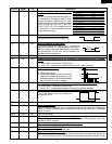

31
R-930AK
R-930AW
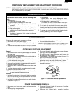
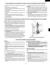
DOOR REPLACEMENT AND ADJUSTMENT
REMOVAL
1. Disconnect oven from power supply and remove the
outer case.
Remove turntable tray and turntable support from oven
cavity.
2. Remove three (3) screws holding lower oven hinge.
3. Remove the lower oven hinge from oven cavity bottom
flange.
4. Remove door assembly from upper oven hinge on the
oven.
5. Door assembly is now free.
Note: When the individual parts are replaced, refer to
"Door Disassembly".
6. On re-installing door, insert the upper oven hinge into the
door hinge pin. Then while holding door in place.
7. Make sure the door is parallel with oven face lines (left
and upper side lines) and door latch heads pass through
latch holes correctly.
8. Insert the lower oven hinge into oven cavity bottom
flange and then engaged the door hinge pin. Then
secure the lower oven hinge firmly with tree (3) mounting
screws.
Note: After any service to the door;
(A) Make sure that door sensing switch and secondary
interlock switch are operating properly. (Refer to
chapter "Test Procedures".).
(B) An approved microwave survey meter should be
used to assure compliance with proper microwave
radiation emission limitation standards.
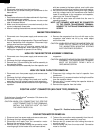
DOOR ADJUSTMENT
The door can be adjusted by keeping screws of each hinge
loose.
After adjustment, make sure of the following :
1. Door latch heads smoothly catch latch hook through
latch holes and that latch head goes through center of
latch hole.
2. Deviation of door alignment from horizontal line of cavity
face plate is to be less than 1.0mm.
3. Door is positioned with its face pressed toward cavity
face plate.
4. Re-install outer case and check for microwave leakage
around door with an approved microwave survey meter.
(Refer to Microwave Measurement Procedure.)
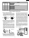
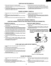
DOOR SENSING SWITCH/SECONDARY INTERLOCK SWITCH AND MONITOR SWITCH REMOVAL
1. Disconnect oven from power supply and remove outer
case.
2. Discharge high voltage capacitor.
3. Remove the control panel assembly, refer to "Control
Panel Removal".
4. Disconnect wire leads from each of the switches and
fuse holder.
5. Remove two (2) screws holding latch hook to oven
flange.
6. Remove latch hook assembly from oven flange.
7. Push outward on the one (1) stopper tabs holding each
of switches place.
8. Switch is now free.
At this time switch lever will be free, do not lose it.
Re-install
1. Re-install switch lever and each interlock switch in its
place. The secondary interlock switch is in the lower
position and the door sensing switch is in the upper
position and the monitor switch is in the middle position.
2. Re-connect wire leads to each switches and fuse holder.
Refer to pictorial diagram.
3. Secure latch hook (with two (2) mounting screws) to
oven flange.
4. Make sure that the monitor switch is operating properly
and check continuity of the monitor circuit. Refer to
chapter "Test Procedure" and Adjustment procedure.
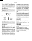
If the door sensing switch, secondary interlock switch and
monitor switch do not operate properly due to a
misadjustment, the following adjustment should be made.
1. Loosen the two (2) screws holding latch hook to the oven
cavity front flange.
2. With door closed, adjust latch hook by moving it back and
forth, and up and down. In and out play of the door
allowed by the latch hook should be less than 0.5mm.
3. Secure the screws with washers firmly.
After adjustment, check the following.
1. In and out play of door remains less than 0.5mm at the
latched position.
2. The door sensing switch and secondary interlock switch
interrupt the circuit before the door can be opened.
3. Monitor switch contacts close when door is opened.
4. Re-install outer case and check for microwave leakage
around door with an approved microwave survey meter.
(Refer to Microwave Measurement Procedure.)
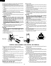
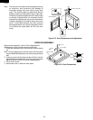
DOOR SENSING SWITCH/SECONDARY INTERLOCK SWITCH AND MONITOR SWITCH ADJUSTMENT
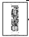
DOOR SENSING
SWITCH
MONITOR FUSE
MONITOR SWITCH
SECONDARY
INTERLOCK
SWITCH
Figure C-4. Latch Switch Adjustments