


15
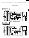
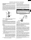
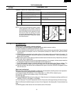
R-930AK
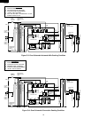
R-930AW
If the capacitor is open, no high voltage will be available to the magnetron. Disconnect input leads and
check for short or open between the terminals using an ohmmeter.
Checking with a high ohm scale, if the high voltage capacitor is normal, the meter will indicate continuity
for a short time and should indicate approximately 10 MΩ once the capacitor is charged. If the above is
not the case, check the capacitor with an ohmmeter to see if it is shorted between either of the terminals
and case. If it is shorted, replace the capacitor.
E SECONDARY INTERLOCK SWITCH TEST
Isolate the switch and connect the ohmmeter to the common (COM.) and normally open (NO) terminal
of the switch. The meter should indicated an open circuit with the door open and a closed circuit with the
door closed. If improper operation is indicated, replace the secondary interlock switch.
F PRIMARY INTERLOCK SYSTEM TEST
DOOR SENSING SWITCH
Isolate the switch and connect the ohmmeter to the common (COM.) and normally open (NO) terminal
of the switch, the meter should indicated an open circuit with the door open and a closed circuit with the
door closed. If improper operation is indicated, replace the door sensing switch.
PRIMARY INTERLOCK RELAY
Disconnect two (2) wire leads from the common (COM.) and normally open (NO) terminal of the primary
Interlock relay (RY2). Check the state of the relay contacts using a ohmmeter. The relay contacts should
be open. If the relay contacts are closed, replace the relay itself.
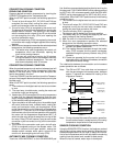
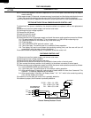
G MONITOR SWITCH
Disconnect the oven from power supply.
Before performing this test, make sure that the secondary interlock switch and the primary interlock relay
are operating properly, according to the above Test Procedures. Disconnect the wire lead from the
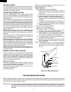
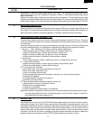
monitor switch (NC) terminal. Check the monitor switch operation by using the ohmmeter as follows.
When the door is open, the meter should indicate a closed circuit. When the monitor switch actuator is
pushed by a screw driver through the lower latch hole on the front plate of the oven cavity with the door
opened (in this condition the plunger of
the monitor switch is pushed in), the
meter should indicate an open circuit.
If improper operation is indicated, the
switch may be defective. After testing
the monitor switch, re-connect the wire
lead to the monitor switch (NC) termi-
nal and check for continuity of monitor
circuit.
SCREW DRIVER
MONITOR SWITCH
OHMMETER
SECONDARY
INTERLOCK
SWITCH
COM.
N.C.
H BLOWN MONITOR FUSE
If the monitor fuse is blown when the door is opened, check the primary interlock relay, secondary
interlock switch, door sensing switch and monitor switch according to the "TEST PROCEDURE" for
those switches before replacing the blown monitor fuse.
CAUTION: BEFORE REPLACING A BLOWN MONITOR FUSE, TEST THE PRIMARY INTERLOCK
RELAY, SECONDARY INTERLOCK SWITCH, DOOR SENSING SWITCH AND MONITOR
SWITCH FOR PROPER OPERATION.
If the monitor fuse is blown by improper switch operation, the monitor fuse and switch must be replaced
with "monitor fuse and switch assembly" part number FFS-BA012WRK0, even if the monitor switch
operates normally. The monitor fuse and switch assembly is packed with 20 ampere fuse and switch.
I TEMPERATURE FUSE TEST
A continuity check across the temperature fuse terminals should indicate a closed circuit unless the
temperature of the magnetron reaches approximately 302˚F (150˚C). If the temperature fuse has
opened, replace the temperature fuse.
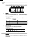
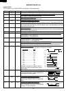
TEST PROCEDURES
PROCEDURE
LETTER
COMPONENT TEST