


28
R-930AK
R-930AW
POSITIVE LOCK
®
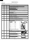
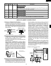
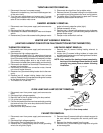
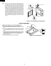
CONNECTOR (NO-CASE TYPE) REMOVAL
Push the lever of positive lock
®
connector. Pull down on the
positive lock
®
connector.
CAUTION: WHEN YOU CONNECTING THE POSITIVE
LOCK
®
CONNECTORS TO THE TERMINALS,
INSTALL THE POSITIVE LOCK
®
SO THAT
THE LEVER FACES YOU.
Figure C-2. Positive lock
®
connector
Terminal
Push
Pull down
1
2
Lever
Positive lock®
connector
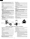
CONVECTION MOTOR REMOVAL
1.
Disconnect oven from power supply and remove outer case.
2. Discharge the high voltage capacitor.
3. Disconnect wire leads from the convection motor.
Remove the convection fan belt.
4. Remove two (2) screws holding the convection motor
mounting angle to the heater duct and base cabinet.
5. Take out the convection motor assembly from the unit.
The convection motor assembly is now free.
6. Remove two (2) screws and nuts holding the motor to
mounting angle.
7. Remove pulley (M) from the motor shaft. Convection
motor is now free.
1. Disconnect oven from power supply and remove outer
case.
2. Discharge the high voltage capacitor.
3. Disconnect the high voltage wire leads and rectifier
assembly from high voltage capacitor and magnetron.
4. Disconnect filament lead of transformer from high voltage
capacitor.
HIGH VOLTAGE CAPACITOR REMOVAL
HIGH VOLTAGE RECTIFIER ASSEMBLY REMOVAL
magnetron.
CAUTION: WHEN REPLACING THE SILICON RECTIFIER
ASSEMBLY, THE GROUND SIDE TERMINAL
MUST BE SECURED FIRMLY WITH A
GROUNDING SCREW.
1. Disconnect oven from power supply and remove outer
case.
2. Discharge the high voltage capacitor.
3. Remove one (1) screw holding the rectifier assembly to
the capacitor holder.
4. Disconnect the rectifier assembly from the capacitor and
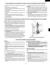
MAGNETRON REMOVAL
1. Disconnect oven from power supply and remove outer
case.
2. Discharge the high voltage capacitor. Disconnect filament
lead of transformer from magnetron. Disconnect high
voltage wire lead from magnetron.
3. Carefully remove four (4) mounting screws hold the
magnetron to waveguide, when removing the screws
holding the magnetron to prevent it from falling.
4. Remove the magnetron from the unit with care so the
magnetron tube should not hit by any metal object
around the tube.
CAUTION: WHEN REPLACING THE MAGNETRON, BE
SURE THE R.F. GASKET IS IN PLACE AND
THE MAGNETRON MOUNTING SCREWS
ARE TIGHTENED SECURELY.
transformer.
5. Disconnect wire leads from the transformer.
6. Remove two (2) screws holding the transformer to the
base cabinet.
Re-install
1. Rest the transformer on the base cabinet with its primary
terminals toward rear cabinet.
2. Insert the two edges of the transformer into two metal
tabs of the base cabinet.
3. Make sure the transformer is mounted correctly to the
corners underneath those tabs.
4. After re-installing the transformer, secure the transformer
with two screws to the base cabinet, one is with outer
tooth washer and the other is without outer-tooth washer.
5. Re-connect the wire leads (primary and high voltage)
and high voltage lead to the transformer and filament
leads of transformer to the magnetron and capacitor,
referring to the “Pictorial Diagram”.
6. Re-install the outer case and check that the oven is
operating properly.
NOTE HOT (ORANGE) WIRE MUST BE CONNECTED
TO THE POWER TRANSFORMER TERMINAL
NEAREST TO THE TRANSFORMER MOUNTING
SCREW.
5. Disconnect high voltage wire lead of capacitor from
transformer.
6. Remove one (1) screw and washer holding the rectifier
from the capacitor holder.
7. Remove one (1) screw holding the capacitor holder to
the rear cabinet.
8. Remove the capacitor from the holder.