


27
R-930AK
R-930AW
COMPONENT REPLACEMENT AND ADJUSTMENT PROCEDURE
CAUTION: DISCONNECT OVEN FROM POWER SUPPLY BEFORE REMOVING OUTER CASE.
DISCHARGE HIGH VOLTAGE CAPACITOR BEFORE TOUCHING ANY OVEN COMPONENTS OR WIRING
AFTER REMOVING OUTER CASE.
OUTER CASE SWITCHES REPLACEMENT
Removal
1. Disconnect the oven from the power supply and remove
the outer case.
2. Discharge high voltage capacitor.
3. Remove the one (1) screw holding the switch holder to
the oven cavity rear plate.
4. Release the one (1) tab of the switch holder from the one
(1) hole of the oven cavity plate.
5. Disconnect the wire leads from the outer case switches.
6. Remove the switch holder (outer case switch assembly)
from the oven cavity rear plate.
7. Push on the one (1) retaining tab holding the outer case
switch.
8. Turn the outer case switch clockwise around the pole.
9. Now, the outer case switch is free.
NOTE: Do not lose the actuator because it will be loose after
the outer case switches are removed.
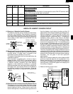
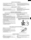
Re-install
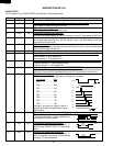
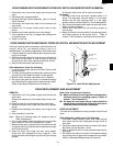
1. Re-install the actuator to the switch holder by inserting
the tab of the actuator into the square hole on the switch
holder, as shown in Figure C-1.
2. Re-install the outer case switches to the switch holder,
as shown in Figure C-1.
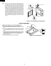
POWER TRANSFORMER REMOVAL
3. Re-connect the wire leads to the outer case switches,
referring to the Pictorial diagram.
4. Re-install the one (1) snap of the main wire harness to
the hole of the switch holder.
5. Catch the one (1) tab of the switch holder to the one (1)
hole of the oven cavity rear plate.
6. Re-install the switch holder (outer case switch assembly)
to the oven cavity rear plate with the one (1) screw.
7. Re-install the outer case cabinet and check that the oven
is operating properly.
Switch
holder
Outer case
switch
Outer case
switch
Actuator
Figure C-1. Outer case switches replacement
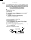
To prevent an electric shock, take the following man-
ners.
1. Before wiring,
1) Disconnect the power supply.
2) Open the door and wedge the door open.
3) Discharge the high voltage capacitor and wait for 60
seconds.
2. Don’t let the wire leads touch to the followiong parts;
1) High voltage parts:
Magnetron, High voltage transformer, High voltage
capacitor and High voltage rectifier assembly.
2) Hot parts:
Oven lamp, Magnetron, High voltage transformer
and Oven cavity.
WARNING FOR WIRING
3) Sharp edge:
Bottom plate, Oven cavity, Weveguide flange,
Chassis support and other metallic plate.
4) Movable parts (to prevent a fault)
Fan blade, Fan motor, Switch, Switch lever, Open
button.
3. Do not catch the wire leads in the outer case cabinet.
4. Insert the positive lock connector certainly until its pin
is locked. And make sure that the wire leads should not
come off even if the wire leads is pulled.
5. To prevent an error function, connect the wire leads
correctly, referring to the Pictorial Diagram.
To remove the components, procedure as follows.
1. Disconnect oven from power supply.
2. Remove screws from rear and along the side edge of
case.
3. Slide the entire case back out about 1 inch (3 cm) to free
OUTER CASE REMOVAL
it from retaining clips on the cavity face plate.
4. Lift entire case from the unit.
CAUTION: DISCONNECT OVEN FROM POWER SUP-
PLY BEFORE REMOVING OUTER CASE.
1. Disconnect oven from power supply and remove outer
case.
2. Discharge high voltage capacitor.
3. Disconnect filament leads of transformer from the
magnetron and capacitor.
4. Disconnect high voltage lead of capacitor from the