


22
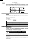
R-930AK
R-930AW
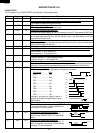
1 VCC IN Connected to GND.
2 VEE IN Anode (segment) of Fluorescent Display light-up voltage: -30V.
Vp voltage of power source circuit input.
3 AVSS IN Power source voltage: -5V.
VC voltage of power source circuit input.
4 VREF IN Reference voltage input terminal.
A reference voltage applied to the A/D converter in the LSI. Connected to GND.(0V)
5 AN7 IN Used for initial balancing of the bridge circuit (absolute humidity sensor). This input is
an analog input terminal from the AH sensor circuit, and connected to the A/D
converter built into the LSI.
6 AN6 IN AH sensor input.
This input is an analog input terminal from the AH sensor circuit, and connected to the
A/D converter built into the LSI.
7-9 AN5-AN3 IN Heating constant compensation terminal.
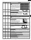
10 AN2 IN Input signal which communicates the door open/close information to LSI.
Door closed; "H" level signal(0V).
Door opened; "L" level signal(-5V).
11 AN1 IN Input signal which communicates the damper open/close information to LSI.
Damper opened; "H" level signal(0V:GND).
Damper closed; "L" level signal(-5V).
12 AN0 IN Temperature measurement input: OVEN THERMISTOR.
By inputting DC voltage corresponding to the temperature detected by the thermistor,
this input is converted into temperature by the A/D converter built into the LSI.
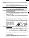
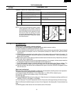
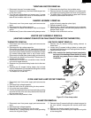
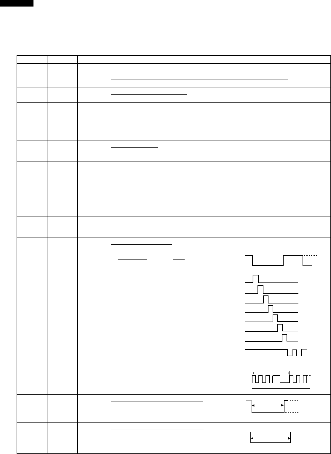
13 P55 OUT Digit selection signal.
The relationship between digit signal and digit are as follows;
Digit signal Digit
P03........................... 1st.
P02.......................... 2nd.
P01........................... 3rd.
P00........................... 4th.
P37........................... 5th.
P36.......................... 6th.
P35.......................... 7th.
P55.......................... 8th.
Normally, one pulse is output in every ß
period, and input to the grid of the Fluores-
cent Display.
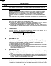
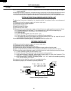
14 P54 OUT Oven lamp and turntable motor driving signal. (Square Waveform : 60Hz)
To turn on and off the shut-off relay(RY1).
The square waveform voltage is delivered to
the relay(RY1) driving circuit.
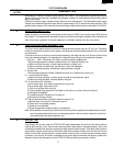
15 P53 OUT Convection motor driving signal.
To turn on and off shut-off relay(RY5). "L"
level during CONVECTION; "H" level other-
wise.
16 P52 OUT Cooling fan motor driving signal.
To turn on and off shut-off relay(RY6). "L"
level during both microwave and convection
cooking; "H" level otherwise.
DESCRIPTION OF LSI
LSI(IZA797DR):
The I/O signals of the LSI(IZA797DR) are detailed in the following table.
Pin No. Signal I/O Description
P03
ß(60Hz)
H
L
GND
VP
P02
P01
P00
P37
P36
P35
P55
ON
OFF
During
cooking
L
GND
H.
(Convection)
ON
OFF
During
cooking
L
GND
H.
During cooking
L
H
16.7 msec.