9
KS-342
Features and panel items
For the most part, the explanations given for the individual
parts of the KS-342 will allow you to operate the mixer effec-
tively. You should therefore read this part of the manual care-
fully in order to understand the many features and operations
possible with the unit.
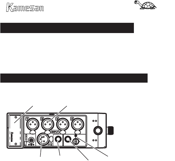
Left side (viewed from front)
This section is chiey the inputs to the mixer:
INPUTS 1 through 4 Connect the microphones or line level
sources to these XLR jacks.
INPUTS 1+2 This XLR-5 jack is used to connect a stereo mi-
crophone to the 1 and 2 inputs. The wiring is: 1= ground, 2=L
+, 3=L –, 4=R +, 5=R –.
Battery locking lever Pull down to release the battery pack
Coaxial power supply Connect a suitable power supply (tip
negative, between 10 V and 15 V, approximately 0.5 A).
DC 12 V OUT This connector is used to supply external power
to other equipment.
AUX IN This connector is used to connect an auxiliary input,
such as a camera’s audio signal, etc.
Aux level control and routing switch The level control is
used to set the level of the input aux signal when it is routed to
the output busses.


