INSTALLATION COMBINATION OVEN
PAGE 10 OPERATOR’S MANUAL 1180963
INSTALLATION
Step 4: Electrical Connections
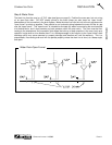
A wiring diagram is located inside the control compartment on the right side of the pull-out control-panel
assembly. To access the control-panel compartment, remove the screw at the top of the control panel and
pull the control panel out.
Units ordered with a 115VAC, 60Hz, single-phase electrical rating are factory-supplied with three-wire cord
and three-prong plug, which fits any standard three-prong grounded receptacle.
Units ordered with a 208/240VAC, 60Hz, single- or three-phase electrical rating are factory-equipped with a
2-pole terminal block located behind a cover plate located at the rear of the unit. To connect the supply
wires, remove the appropriate cover plate. Route the supply wires and the grounding wire through the strain
relief fitting to the terminal block. Insert the supply wires, one each, into the two poles of the terminal block
and tighten the screws. Insert the ground wire into the grounding lug and tighten the screw. Re-attach the
cover plate.
Three phase units are wired as above, using only two supply wires. The third wire is not used and must be
properly terminated.
All units are shipped wired as specified by factory order. Conversion between single-phase and three-phase
can be accomplished by referring to phase loading and line amperes chart on wiring diagram for wire size
and ampere requirements.
! WARNING
A POSITIVE GROUND CONNECTION IS ESSENTIAL. DO NOT ALLOW ANY TAMPERING OR
ADJUSTMENT OF ANY CONTROL OR WIRING. THE UNIT IS FACTORY SET. ADJUSTING ANY
INTERNAL COMPONENT OTHER THAN THE MAIN FUSE BLOCK CAN VOID THE WARRANTY.
! WARNING
ELECTRICAL GROUNDING INSTRUCTIONS
This appliance is equipped with a three-prong (grounding) plus for your protection against shock
hazard and should be plugged directly into a properly grounded three-prong receptacle. Do not cut or
remove the grounding prong from the plug.
Step 5: Connect Water Supply
Connect a cold water line to the 3/8" female NPT "tee" connector located on the back of the oven (at the
lower left-hand side when facing the back of the oven, see figure on page 9).
To facilitate cleaning, plus allow access to the rear of the unit, flexible connections are recommended.
NOTICE: WATER SPECIFICATION
To meet warranty requirements, supply water must meet the following specification:
Pressure ...........................................30 to 60 psi (205 to 410 kPa)
Total Dissolved Solids (TDS) ...........60 PPM
Hardness ..........................................2 Grains or 35 PPM
pH Factor..........................................7.0 to 7.5


