


SFG10E ELECTRIC SURFACE GRINDER — OPERATION AND PARTS MANUAL — REV. #1 (07/16/07) — PAGE 31
ASSEMBLY INSTRUCTIONS/OPERATIONS
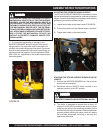
Maintenance/Service
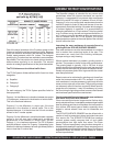
PREVENTATIVE MAINTENANCE CHECK LIST
The normal operation of the SURFACE GRINDER produces
extreme dirt and dust, along with levels of random vibration.
Before operating the SURFACE GRINDER, the following
service list should be accomplished. This list is for reference
only and is not intended to be all inclusive. Other subject
areas can be added at the discretion of the owner(s) and/or
operator(s):
1) Check all fasteners for proper torque values. If a fastener
requires re-torquing, consult a torque chart for proper
value. Properly discard and replace any worn fastener
with a factory approved, replacement part.
2) Check the V-belts for wear. Adjust or replace as
necessary. Check pulleys for wear and proper alignment.
Many loose materials created as a result of operating
processes can be extremely abrasive.
3) Keep the SURFACE GRINDER clean. Wash the unit
after each use. Determine that the interior sections of
the frame are free of material build-ups. Such build-ups
can restrict the operating process and present a potential
safety hazard. Clean and remove any material build-up
from the SURFACE GRINDER after each use.
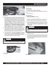
4) Remove material accumulations from the exterior
surfaces of the electric motor. The electric motor is a
totally enclosed, fan cooled (TEFC) design. Keep the
fan fins clear of material accumulations to enhance
airflow over the motor exterior for cooling purposes.
DANGERDANGER
DANGERDANGER
DANGER
DO NOT PERFORM PREVENTATIVE MAINTENANCE
CHECKS WITH THE ELECTRIC MOTOR RUNNING.
STOP THE POWER SOURCE AND DISCONNECT THE
SPARK PLUG OR EXTENSION CORD BEFORE PER-
FORMING ANY MAINTENANCE TO THE SURFACE
GRINDER. TURN THE ON/OFF SWITCH TO THE OFF
POSITION BEFORE RECONNECTING THE EXTEN-
SION CORD. IMPROPER PROCEDURES CAN
RESULT IN PROPERTY DAMAGE AND/OR PER-
SONAL INJURY.
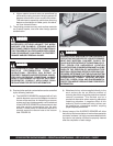
CHECKING V-BELT TENSION AND ALIGNMENT
Proper V-belt tension and alignment are essential for smooth
transmission of horsepower and extended service life.
Improper tension and alignment will accelerate V-belt wear
and contribute to decreased productivity. The V-belt is
tensioned at the factory with the maximum recommended
tension force. Check the belt tension at least two times
during the first day of operation as there will normally be a
rapid decrease in belt tension until it has been run in. Check
the belt tension every eight hours of operation thereafter
and maintain tension within the recommended range. The
correct operating tension for a V-belt drive is the lowest
tension at which it will not slip under peak load conditions.
Tools Required:
1 16 inch minimum length straightedge.
1 10 lbs minimum capacity, tension scale or belt tension
tool.
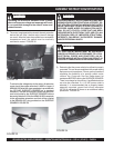
1) Disconnect the extension cord or SURFACE GRINDER
from the power source.
2) Position the SURFACE GRINDER on a suitable work
bench with the V-belt approximately at waist level.
3) Remove the belt guard from the main frame. Clean the
inside of the belt guard with an appropriate solvent.
Check for signs of wear and damage.
Observe all applicable safety precautions for the
solvent.
CAUTION
CAUTIONCAUTION
CAUTIONCAUTION
CAUTION
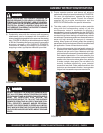
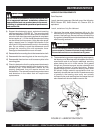
4) Check the belt tension using the spring scale or belt
tension tool midway between the engine clutch pulley
and the transmission pulley. Belt tension should mea-
sure approximately 0.22 inch at 3-1/4 to 4-3/8 lbs.
measured force range. FIGURE 41. If tension is within
specifications, proceed to Step 5. If tension is not within
specifications, refer to INSTALLING A REPLACEMENT
V-BELT for specific information.