


SFG10E ELECTRIC SURFACE GRINDER — OPERATION AND PARTS MANUAL — REV. #1 (07/16/07) — PAGE 32
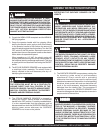
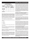
FIGURE 41
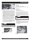
5) Belt alignment is checked with the straightedge. Place
the straightedge squarely against the transmission
pulley. Properly aligned pulleys should also place the
straightedge squarely against the motor pulley. Remove
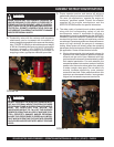
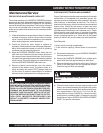
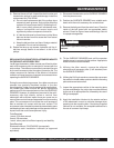
the straightedge and rotate the motor pulley 120
degrees. FIGURE 42. Recheck alignment with the
straightedge. Repeat the process until the motor pulley
is rotated a full 360 degrees. Maximum allowable
misalignment is + - 1/32 inch. If pulley alignment is not
within specifications, refer to INSTALLING A
REPLACEMENT V-BELT for specific information.
6) Install the belt guard to the main frame. Determine that
all safety related decals affixed to the belt guard are
fully readable. If any decal is not fully readable, replace
with a factory approved, replacement part only.
7) If the machine is to be used immediately, reconnect
the extension cord or SURFACE GRINDER to the power
source. Determine that the ON/OFF switch located on
the operator handle is in the OFF position
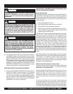
DANGERDANGER
DANGERDANGER
DANGER
UNEXPECTED MACHINE START UP CAN RESULT IN
PROPERTY DAMAGE AND/OR PERSONAL INJURY.
FIGURE 42
INSTALLING A REPLACEMENT V-BELT OR PULLEY
Tools Required:
2 1/2 wrenches.
1 16 inch minimum length straightedge.
1 10 lbs minimum capacity, tension scale or belt tension
tool.
1 belt tension tool.
Parts Required:
1 V-Belt, P/N SFB45
1 Pulley Assy. P/N SFSG120400
1) Position the SURFACE GRINDER on a suitable work
surface with the V-belt approximately at waist level.
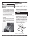
2) Remove the belt guard from the main frame. Clean the
inside of the belt guard with an appropriate solvent.
Check for signs of wear and damage. Secure in a proper
storage area.
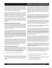
Observe all applicable safety precautions for the
solvent.
CAUTION
CAUTIONCAUTION
CAUTIONCAUTION
CAUTION
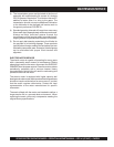
3) Using the 1/2-inch wrenches, loosen the motor mounting
plate cap screws.
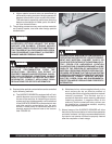
4) With the same wrenches, rotate the motor take-up cap
screws counterclockwise to loosen the V-belts and allow
the electric motor to slide toward the front of the main
frame. FIGURE 43.
FIGURE 43
MAINTENANCE/SERVICE