


Part # 4523343 Rev 1 (02/12/08) Page 7
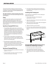
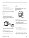
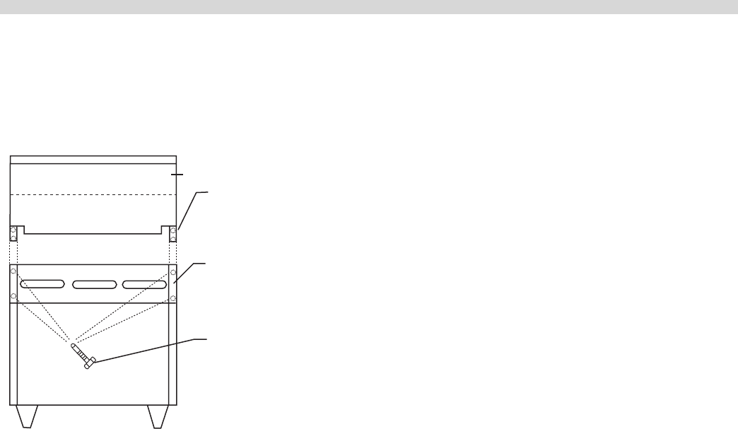
3. Securely fasten the support brackets to the burner box
sides with (4) #14 x 5/8” Hex washer head, type B tapping
screws. (Hardware package is supplied).
Upright
Main Body
Side
#14 x 3/4"
Type "B"
Washer Hex
Head Sheet Metal
Screws (4 Req'd)
Ventilation Air
The following notes are intended to give general guidance.
For detailed recommendations, refer to the applicable
code(s) in the country of destination.
Proper ventilation is critical for optimum performance. The
ideal method of ventilating open-top equipment is the use
of a properly designed canopy that should extend six inches
(152 mm), beyond all sides of the appliance(s) and six feet, six
inches (1981mm) above the oor.
A strong exhaust will create a vacuum in the room. For an
exhaust vent to work properly, replacement air must be
equal to the amount of exhausted.
All gas burners and pilots need sucient air to operate. Large
objects should not be placed in front of the appliance(s) that
would obstruct the ow of air into the front.
Statutory Regulations
The installation of this appliance must be carried out by
a competent person and in accordance with the relevant
regulations, codes of practice and the related publications of
the country of destination.
The installation must conform to the National Fuel Gas Code
ANSI Z223.1, or latest edition, NFPA No.54 - latest edition/or
local code to assure safe and ecient operation. In Canada,
the installation must comply with CSA B149.1 and local
codes.
Gas Connection
The local gas authority should be consulted at the
installation planning stage in order to establish the
availability of an adequate supply of gas and to ensure
that the meter is adequate for the required ow rate. The
pipe work from the meter to the appliances must be an
appropriate size.
All xed (non-mobile) appliances MUST be tted with
an accessible Upstream gas shut o valve as a means of
isolating the appliance for emergency shut o and for
servicing. A union or similar means of disconnection must be
provided between the gas-cock and the appliance.
A manually operable valve must be tted to the gas supply
to the kitchen to enable it to be isolated in an emergency.
Wherever practical, this shall be located either outside the
kitchen or near to an exit in a readily accessible position.
Where it is not practical to do this, an automatic isolation
valve system shall be tted which can be operated from a
readily accessible position near to the exit.
In locations where the manual isolation valve is tted or the
automatic system can be reset a notice MUST be posted
stating:
“ALL DOWNSTREAM BURNER AND PILOT VALVES MUST
BE TURNED OFF PRIOR TO ATTEMPTING TO RESTORE THE
SUPPLY. AFTER EXTENDED SHUT OFF, PURGE BEFORE
RESTORING GAS.”
Installation Notes
Before assembly and connection check gas supply.
A. The type of gas for which the unit is equipped is stamped
on the data plate located behind the lower front panel.
Connect a unit stamped “NAT” only to natural gas;
connect one stamped “PRO” only to propane gas.
INSTALLATION Continued