


Part # 4523343 Rev 1 (02/12/08)Page 8
B. If it is a new installation have the gas authorities check
meter size and piping to assure that the unit is supplied
with necessary amount of gas pressure required to
operate the unit.
C. If it is additional or replacement equipment have the gas
authorities check pressure to make certain that existing
meter and piping will supply fuel to the unit with no
more than 0.15 Kpa pressure drop.
D. Make certain new piping and connections have been
made in a clean manner and have been purged so that
piping compound, chips, etc. will not clog pilots, valves or
burners. Use pipe joint compound approved for natural
and liqueed petroleum gases.
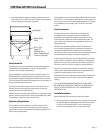
INSTALLATION Continued
NOTE: Gas pressure should be checked when the unit is
installed and all other equipment on the same line is on. The
operating gas pressure must be the same as that specied
on the rating plate. If necessary, pressure adjustment may be
made at the pressure regulator supplied with the appliance.
The appliance and its individual shut-o valve must be
disconnected from the gas supply piping system during any
pressure testing of that system where pressures are in excess
of 1/2 PSIG (3.45kPa.)
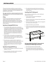
Final Preparation
NOTE: Your new range has a plastic coating to help
protective the nish from scratches during shipping. This
protective plastic lm should be pealed o prior to starting
the range.
TESTING AND ADJUSTMENT
Testing
All ttings and pipe connections must be tested for
leaks. Use approved gas leak detectors, soap solution or
equivalent, checking over and around all the ttings and
pipe connections. DO NOT USE A FLAME! Accessibility to
all gas lines and ttings require that valve panel(s) lower
front panel(s), and/or oven rack(s) be removed. It may be
necessary to remove, or at least raise and securely prop
griddle(s), hot top(s), and/or top grate(s). All parts removed,
(including fasteners), should be stored safely for re-
installation.
1. Be sure that all valves and thermostats are in the “OFF”
position.
2. Turn on the main gas supply valve. Light all top section
pilots.
3. Leak test all valves and ttings as described at the
beginning of this section. Correct any leaks as required
and recheck.
4. Light the oven pilot.
5. Set the oven thermostat to maximum. Leak test all valves
and ttings as described at the beginning of this section.
Correct any leaks as required and recheck.
6. Shut o all valves and set thermostat dials to “OFF” or
lowest position. All units are tested and adjusted at the
factory, however, burners and pilots should be checked
upon installation and adjusted if necessary.
CAUTION: Gas will ow to the top section burners even if
top section pilots are not lit. Gas will not be interrupted. It
is the responsibility of the operator to conrm the proper
ignition of each burner as it is turned on. Should ignition
fail to occur 4 seconds after turning a burner on, turn the
burner o, wait 5 minutes, and try again.