


1
Model C300 NP To the Installer
071010
Section 1 To the Installer
The Model C300NP is designed for indoor use only.
DO NOT installthemachineinanarea
where a water jet could be used. Failure to follow
this instruction may result in serious electrical shock.
Air Cooled Units
Air cooled units require a minimum of 3” (76 mm) of
air space on the rear and left side to the top of the
unit, 0” on the right side, and 12” (305 mm) to the
ceiling. This is required to allow for adequate air flow
through the condenser(s). Failure to allow adequate
clearance can reduce the refrigeration capacity of
the freezer and possibly cause permanent damage
to the compressor(s).
Water Cooled Refrigeration Units
(Water Cooled Units On ly)
On the back of the unit, two additional 3/8” (9.5 mm)
F.P.T. water connections for condenser inlet and
outlet have been provided for easy hook-up. 3/8”
(9.5 mm) inside diameter water lines should be
connected to the machine. Flexible lines are
recommended if local codes permit. Failure to use
adequate size water lines may cause the unit to go
on high head pressure and shut down.
Depending on local water conditions, it may be
advisable to install a water strainer to prevent
foreign substances from clogging the automatic
water valve.
DO NOT INSTALL A HAND SHUT-OFF VALVE ON
THE “OUT” LINE! Water cooled units are counter
flow and the water should flow in this order: First
through the automatic water valve. Second, through
the inlet located at the bottom of the condenser.
Third, through the outlet fitting located at the top of
the condenser toanopentrapdrain.
IMPORTANT: Water pressures are pre-set at the
factory. Do not adjust the water pressure.
Improper water adjustments may cause operation
discrepancies.
Water Connections
An adequate cold water supply must be provided
with a hand shut-off valve. On the back of the unit, a
3/8” (9.5 mm) male flare water connection has been
provided for easy hook-up. A flexible line is
recommended, if local codes permit. A minimum of
25 psi water pressure is required to avoid having the
unit cut out the low water pressure switch. A booster
pump must be provided if this pressure is not
available. It is always a good practice to have a filter
system to improve the quality of the water and to
avoid clogging the operating components.
Note: Water lines beyond 200 ft. (61 m) require 1/2”
(13 mm) water lines.
INSTALL POTABLE WATER CONNECTION
WITH ADEQUATE BACK-FLOW
PROTECTION TO COMPLY WITH
APPLICABLE NATIONAL, STATE AND
LOCAL CODES.
It is always a good practice to have a filter system to
improve the quality of the water and to avoid
clogging the operating components.
IMPORTANT: The water filter (064422-SER) must
be thoroughly flushed with water before connecting it
to the machine. This removes any loose particles
present from the manufacture of the filter that could
clog the flow control. To flush the filter, connect the
inlet end of the filter to the water supply. Position the
outlet end of the filter over an empty pail. Open the
water supply. Allow water to flow through the filter
until the water exiting the filter is clear. Close the
water supply. Attach the outlet end of the filter to the
machine. Reopen the water supply.
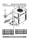
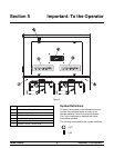
Figure 1