


GB
15
space of at least 20 mm should be left at
the back of the cupboard. As an alternati-
ve to this type of panel, you can install a
detachable protective cover to the bottom
of the hob, which can be obtained from our
Technical Services using the reference in-
dicated.
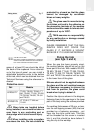
When hobs are handled before
being installed, care should be taken in
case there is any protruding part or
sharp edge which could cause injury.
When installing units or applian-
ces above the hob, the hob should be
protected by a board so that the glass
cannot be damaged by accidental
blows or heavy weights.
The glues used in manufacturing
the kitchen unit and in the adhesive on
the decorative laminate of the worktop
surface should be made to tolerate tem-
peratures of up to 100ºC.
TEKA assumes no responsibility
for any malfunction or damage caused
by faulty installation.
PLEASE REMEMBER THAT THE GUA-
RANTEE DOES NOT COVER THE
GLASS IF IT SUFFERS A VIOLENT
BLOW OR IF IT IS USED IMPROPERLY.
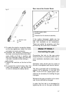
Fixing the hob
(see figs. 3 and 4)
When the gap has been properly sized,
the sealing washer should be put on the
lower part of the hob. With models VR 622,
TR 620, TR 640, TT 640, TT 600, TB 600,
TR 600, TT 630, TR 735 AB, TM 620, TR
641 and TM 601 the washer will be stuck
to the lower face of the glass.
Silicone should not be applied between
the glass and the unit worktop because
if it becomes necessary to remove the
hob from its position, the glass could
break when trying to detach it.
Position the clips as shown in the diagram,
fastening them to the openings in the lower
part of the body using the screws provided.
For worktop thicknesses of 30 mm. or less,
use the self-tapping screws (M5) that are
provided as a fastening accessory - put
them into the clip’s round hole. This hole
will be threaded as the screw is inserted
into it, and this should be done before fi-
xing the clip to the worktop.
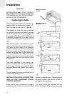
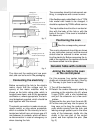
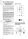
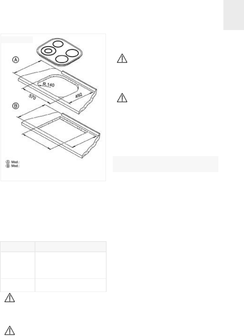
VTN DC and TC 620
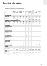
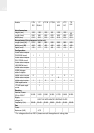
Rest of the models The dimensions L and W are
shown in the table "Dimensions and characteris-
tics" of the Technical Information section.
fig. 2
Fitting holes
m
a
x
i
m
u
n
5
7
5
m
a
x
i
m
u
n
5
7
5
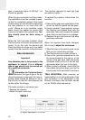
Ref. Models
81253177
TT 600, TB 600, TR 640, TT
640, TR 620, TT 630, TR 600,
TR 735 AB, TM 620, TR 641
and TM 601
81253176
VT TC 60.3, TT 620 and
TC 620
Protective cover
W
L