


GB
16
The clips and the sealing joint are provi-
ded, and can be found in the packaging.
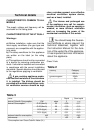
Connecting the electricity
Before connecting the hob to the electric
mains, check that the voltage and fre-
quency of the mains matches what is
shown on the hob’s rating plate, which is
located lower down, and on the guarantee
certificate or, where appropriate, the tech-
nical datasheet supplied, which should be
kept together with this manual.
The electric connection is made via an om-
nipolar switch or plug where accessible,
which is suitable for the intensity to be to-
lerated and which has a minimum gap of 3
mm between its contacts, which will ensu-
re disconnection in case of emergency or
when cleaning the hob.
The connection should include correct ear-
thing, in compliance with current norms.
If the flexible supply cable fitted to the VT CM
hob model ever needs to be changed, it
should be replaced by TEKA’s official service.
The input cable should not be in contact ei-
ther with the body of the hob or with the
body of the oven, if the oven is installed in
the same unit.
Positioning the oven
See the corresponding manual.
The oven’s placement should be as shown
in your instruction manual, and the manual
should also be referred to when connec-
ting the electricity. Before accessing the in-
side of the appliance, the appliance should
be disconnected from the power.
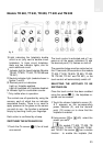
Ceramic hobs with controls
Joining the hob to the oven
or the control panel
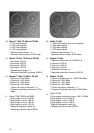
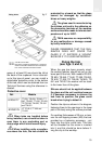
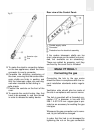
For this purpose, four cardan telescopic
shafts are included with the hob. (See fig.
5). The way to join them is as follows:
1 Turn off the electricity.
2 Detach the cardan telescopic shafts by
pressing on the retention clip (A), where
it says PUSH, with a slim screwdriver,
and pull the extension out a few centi-
metres.
3 Remove the four pins from the ends (B).
4 Put the oven part-way into its space, ta-
king care not to drag the cardan teles-
copic shafts coming from the hob, and
leaving enough space to put in the other
ends of the telescopic shafts into the
shafts in the rear part of the control
panel, and then replace the pins. (See
fig. 5)
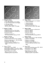
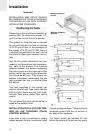
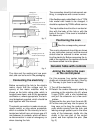
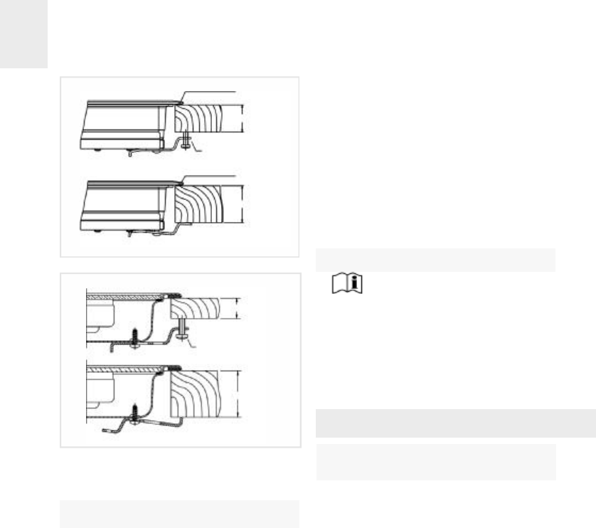
40 mm
20/30 mm
Self-tapping screw for 20
and 30 mm thick worktops
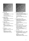
40 mm
20/30 mm
Self-tapping screw for 20
and 30 mm thick worktops
Sealing joint
Sealing joint
fig. 3
fig. 4