GB
17
5 To make the electric connection betwe-
en the two appliances, attach the hob’s
connector to oven’s connector.
6 Complete the definitive positioning of
the oven, ensuring that the cardan teles-
copic shafts are firmly in position and
that the telescopic pipes are well-alig-
ned when inserted so that sliding is
quite simple.
7 Position the controls on the front of the
oven.
8 To operate the control knobs, they first
have to be pressed in, and then turned
in order to release the safety device.
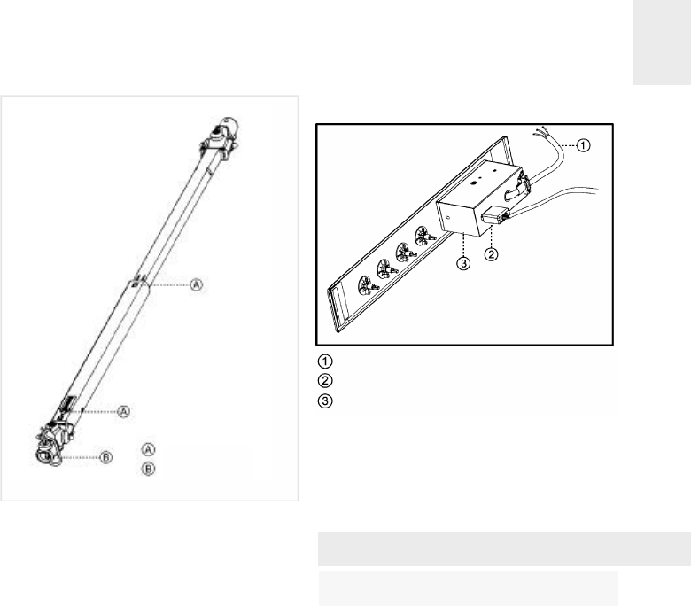
Rear view of the Control Panel:
If the cardan telescopic shafts are too
short, extensions can be added (not provi-
ded, but available as an accessory).
These are added by pressing, and they
are fixed by the cover that is included.
Model VT DUAL.1
Connecting the gas
Connecting the hob to the gas mains
should be done in compliance with the cu-
rrent installation standards and/or regula-
tions.
Ventilation slots should also be made at
the site in compliance with current norms.
The hob is provided with a threaded con-
nection 1/2” in diameter, in line with ISO
228-1. A Ø 10/12 mm. copper pipe is pro-
vided as an accessory for welding the gas
inlet pipe.
Whenever the gas connection nut is remo-
ved, its joint should be changed.
In order that the hob is not damaged by
tightening the nut on the gas connection
fig. 5
Retention clips
Pins
fig. 6
Flexible supply cable
Connector
Protective box for electrical assembly


