


12
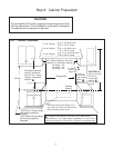
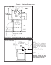
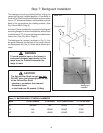
Step 5: Gas Requirements and Hookup
Verify the type of gas being used at the installation site.
The appliance is shipped from the factory for use
with natural gas. It must be converted for use with
propane. A qualified technician or installer must
do the conversion. Make certain the range matches
the type of gas available at this location.
The field conversion kit for this series of dual-fuel
ranges is Thermador Model PLPKIT. Obey all instruc-
tions in PLPKIT for correct conversion of the gas
regulator and settings for the gas valves.
HOOK UP
• A manual gas shut-off valve must be installed
external to the appliance, in a location accessible
from the front, for the purpose of shutting off the
gas supply. The supply line must not interfere with
the back of the unit. Make sure the gas supply is
turned off at the manual shut-off valve before
connecting the appliance.
• The range is supplied with its own pressure regu-
lator that has been permanently mounted within
the range body.
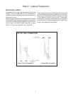
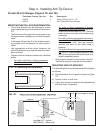
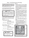
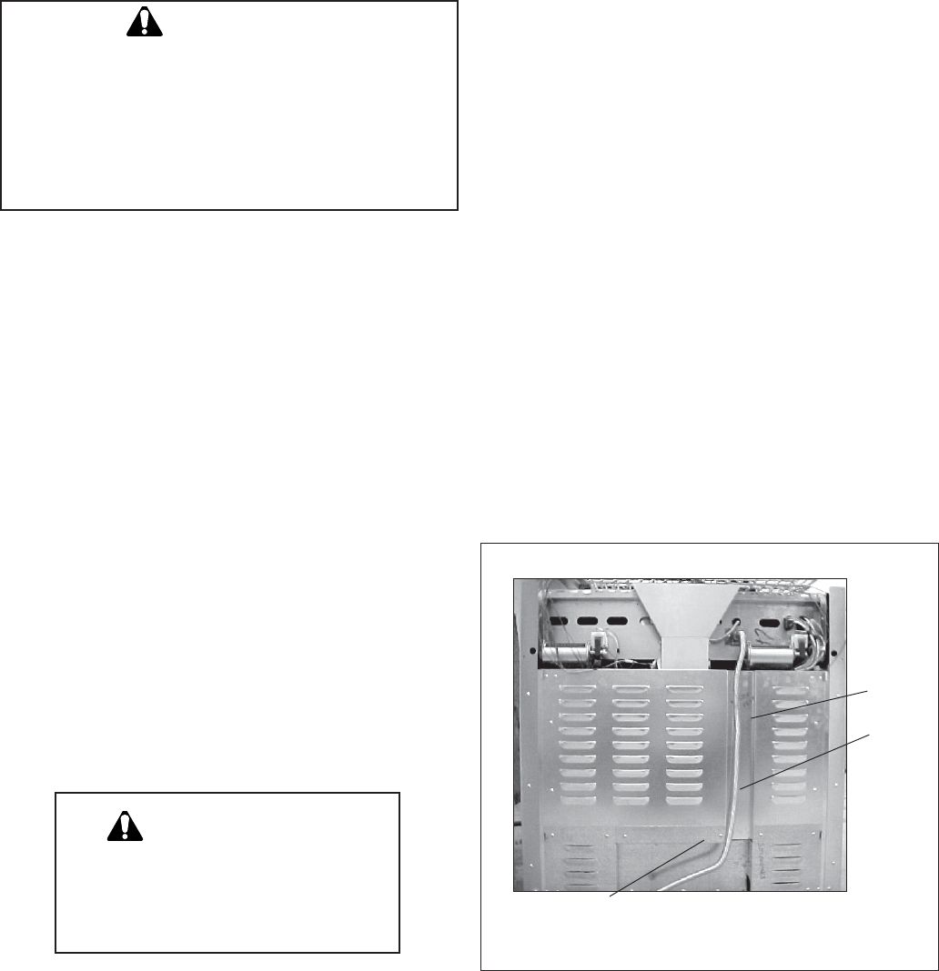
• Use 3/4" flex line to connect between the gas
supply and the appliance manifold pipe, which
exits the upper rear of the appliance. The appli-
ance manifold pipe connection has a 3/4" NPT
external thread and a 1/2" NPT internal thread.
(See Photo A.) Use caution to avoid crimping the
3/4" flex line when making bends.
• The gas supply connections shall be made by a
competent technician and in accordance with
local codes or ordinances. In the absence of a
local code, the installation must conform to the
National Fuel Gas Code ANSI Z223.1/NFPA54-
current issue.
• Always use pipe sealing compound or Teflon
®
tape on the pipe threads, and be careful not to
apply excessive pressure when tightening the
fittings.
• Leak testing of the appliance shall be in accor-
dance with the following instructions.
• Turn on gas and check supply line connections
for leaks using a soap and water solution.
• Bubbles forming indicate a gas leak. Repair all
leaks immediately after finding them.
• Do not use a flame of any kind to check for
gas leaks.
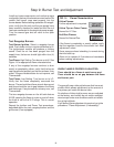
Natural Gas Requirements:
Inlet Connection: 3/4" NPT external
1/2" NPT internal
(Minimum 3/4" diam. flex line.)
Supply Pressure: 6" min. to 14" max. water col-
umn.
(14.9 to 34.9 mb)
Manifold Pressure: 5" water column (12.5 mb)
Propane Gas Requirements:
Inlet Connection: 3/4" NPT external
1/2" NPT internal
(Minimum 3/4" diam. flex line.)
Supply Pressure: 11" min. to 14" max. water col-
umn.
(27.4 mb to 34.9 mb)
Manifold Pressure: 10" water column (24.9 mb)
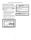
Use 3/4" flex line to connect between the gas
supply and the appliance manifold pipe, which
exits the upper rear of the appliance.
Photo A
Channel
for gas
line
➤
➤
This appliance has been CSA certified for safe opera-
tion up to an elevation of 10,200 ft. without any modi-
fications. Exception: For use with propane, the appli-
ance must be converted per the LP conversion in-
structions.
When connecting unit to propane gas, make
certain the propane gas tank is equipped with its
own high pressure regulator in addition to the
pressure regulator supplied with the appliance.
The pressure of the gas supplied to the appli-
ance regulator must not exceed 14"
(34.9 mb) water column.
CAUTION
WARNING
Gas line must not come in contact
with any components inside back
cover of range. Run gas line in
channel in back of range.