


6
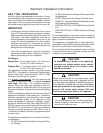
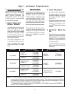
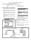
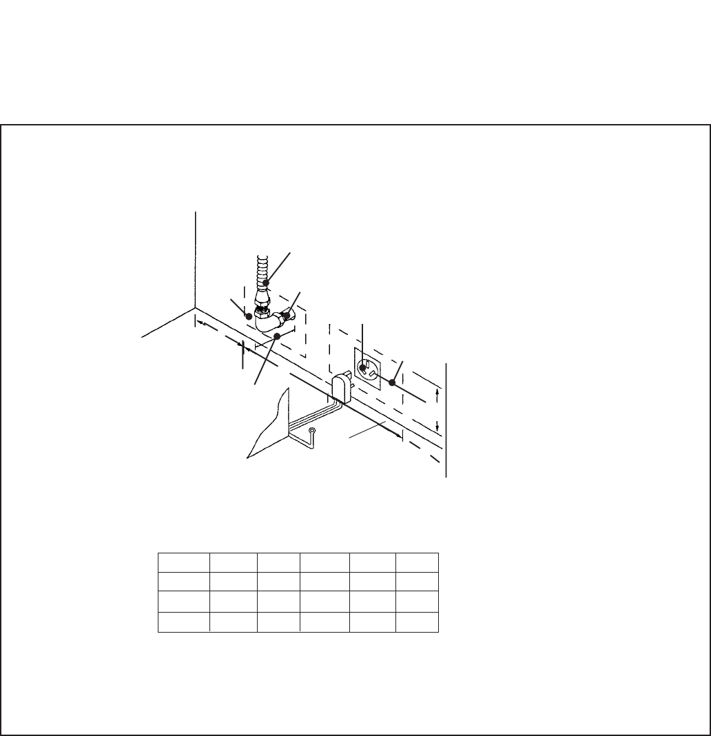
GAS AND ELECTRIC SUPPLY ZONES:
Step 2: Cabinet Preparation
Typical place-
ment shown.
Other placement
of Gas Supply
and Electrical
Receptacle
within the Elec-
trical and Gas
Supply Zone is
acceptable.
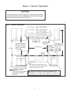
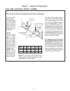
FIG. 3A Gas & Electrical Supply Zone for Dual Fuel Ranges
The Dual Fuel ranges may be
connected to the power supply
with a range supply cord kit or by
hard-wiring to the power supply.
It is the responsibility of the in-
staller to provide the proper wir-
ing components (cord or conduit
and wires) and complete the elec-
trical connection as dictated by
local codes and ordinances, and/
or the National Electric Code. The
units must be properly grounded.
Refer to Step 6 for details.
The range must be connected
only to the type of gas for which
it is certified. If the range is to be
connected to propane gas, en-
sure that the propane gas supply
tank is equipped with its own high
pressure regulator in addition to
the pressure regulator supplied
with the range. (See Step 5.)
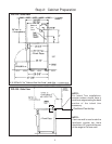
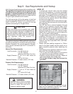
NOTE: Any opening in the wall behind the
appliance and any opening in the floor under
the appliance must be sealed.
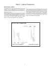
NOTE:
If not already
present, install
gas shut-off
valve in an eas-
ily accessible
location. Make
sure all users
know where and
how to shut off
the gas supply
to the range.
NOTE: The in-
staller should
inform the con-
sumer of the lo-
cation of the gas
shut-off valve.
Model A B C D E
30" 8" 12" 10" 6-1/2" 5-1/4"
36" 10-1/2" 15" 10-1/2" 6-1/2" 5-1/4"
48" 16-1/2" 16" 15-1/2" 6-1/2" 5-1/4"
3/4" Flex Line
to Appliance
A
Centerline of
Electrical
Supply Zone
Gas
Supply
Zone
1/2"
NPT
240 VAC Receptacle
(Shown) or Junction
Box
2" Maximum Protru-
sion from Wall for
Gas Supply
➤
➤
➤
➤
➤
➤
D
Floor
E
➤
➤
B
➤
➤
C