


English 17
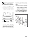
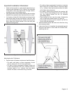
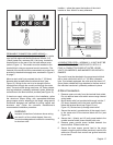
PERMANENT CONNECTION (HARD WIRING) —
Units may be hard wired to the power supply. The installer
must provide approved flexible aluminum conduit, 3/4”
(19mm) trade size, maximum 6ft (1.8m) long. Locate the
terminal block on the rear of the unit and remove cover
(refer to Figure 11). The conduit must be installed to the
terminal block using an approved conduit connector. The
free end of the conduit must be connected to a junction box
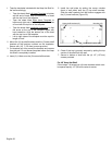
provided in the electrical supply zone, as shown in Figure 3
on page 7.
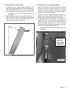
Mount a strain relief (not provided) into the 1" (25.4mm)
diameter hole located below the terminal block (see
Figure 13). Wiring for the unit is to be brought into the
terminal block through the conduit and through the strain
relief. The ends of the wiring must have 1/4” faston closed-
loop lugs attached, preferably soldered in place. Make the
connections to the terminal block provided (see Figure 12).
If aluminum supply wiring exists in the installation, splice
the aluminum house wiring with appropriate-thickness
gauge copper wire for adapting to the range, using special
connectors designed and certified for joining copper and
aluminum wire. Follow the connector manufacturer’s
recommended installation procedure.
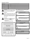
WARNING:
Improper connection of aluminum house wiring
can result in a fire or shock hazard. Use only
connectors designed and certified for connecting
to aluminum wire.
Installer — show the owner the location of the circuit
breaker or fuse. Mark it for easy reference.
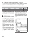
4-CONDUCTOR CORD— NORMALLY, A UNIT MUST BE
CONNECTED TO THE POWER SUPPLY WITH A 3-
POLE, 4-CONDUCTOR CORD KIT RATED 125/250
VOLTS, 50 AMPERES, AND MARKED FOR USE WITH
RANGES.
The cord kit must be attached to the range terminal block
with a strain relief which will fit a 1" (25.4mm) diameter
hole. If not already equipped, the cord must also have 1/4”
(6mm) faston closed-loop lugs attached to the free ends of
the individual conductors, preferably soldered in place.
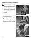
4-Wire Connection
1. Remove upper nuts only from the terminal block studs.
Do not remove lower nuts which secure range internal
wiring leads.
2. Mount strain relief (not provided with range) into the 1"
(25.4mm) diameter hole in the back panel located
below the terminal block (see Figure 13 and
Figure 12). Route wires up through strain relief.
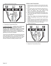
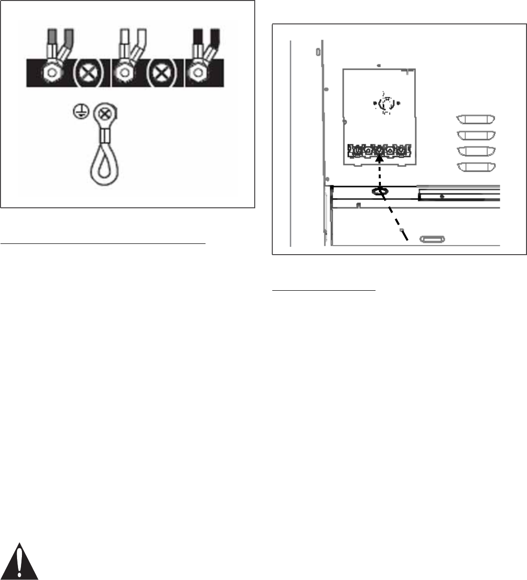
3. Secure the neutral, grounded wire of the supply circuit,
to the center stud of the terminal block with nut (see
Figure 14).
4. Secure the L1 (black) and L2 (red) power leads to the
outside terminal studs (brass colored) with nuts.
5. Remove green ground screw located beneath the
terminal block. Discard white wire.
6. Secure the bare copper ground lead to the range
chassis using the ground screw previously used for the
white wire. Be sure that neutral and ground terminals
do not touch.
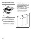
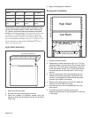
Figure 12: Terminal Block
Figure 13: Strain Relief Location
Terminal Block
Strain
Relief